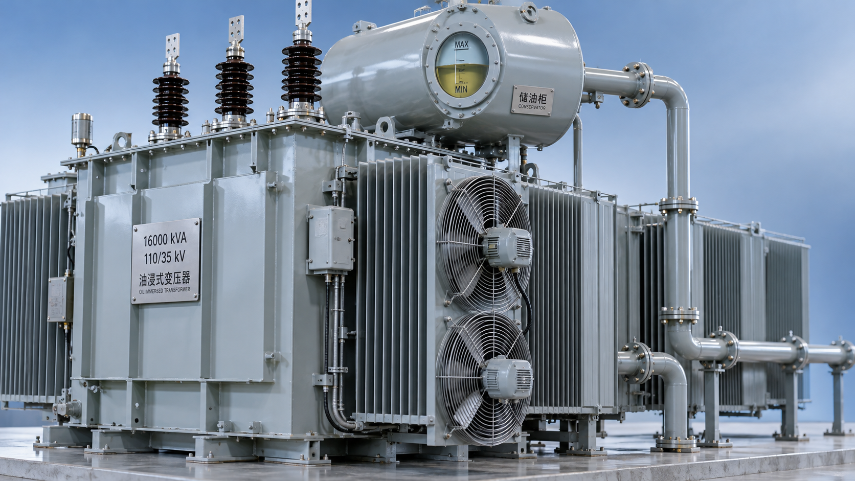
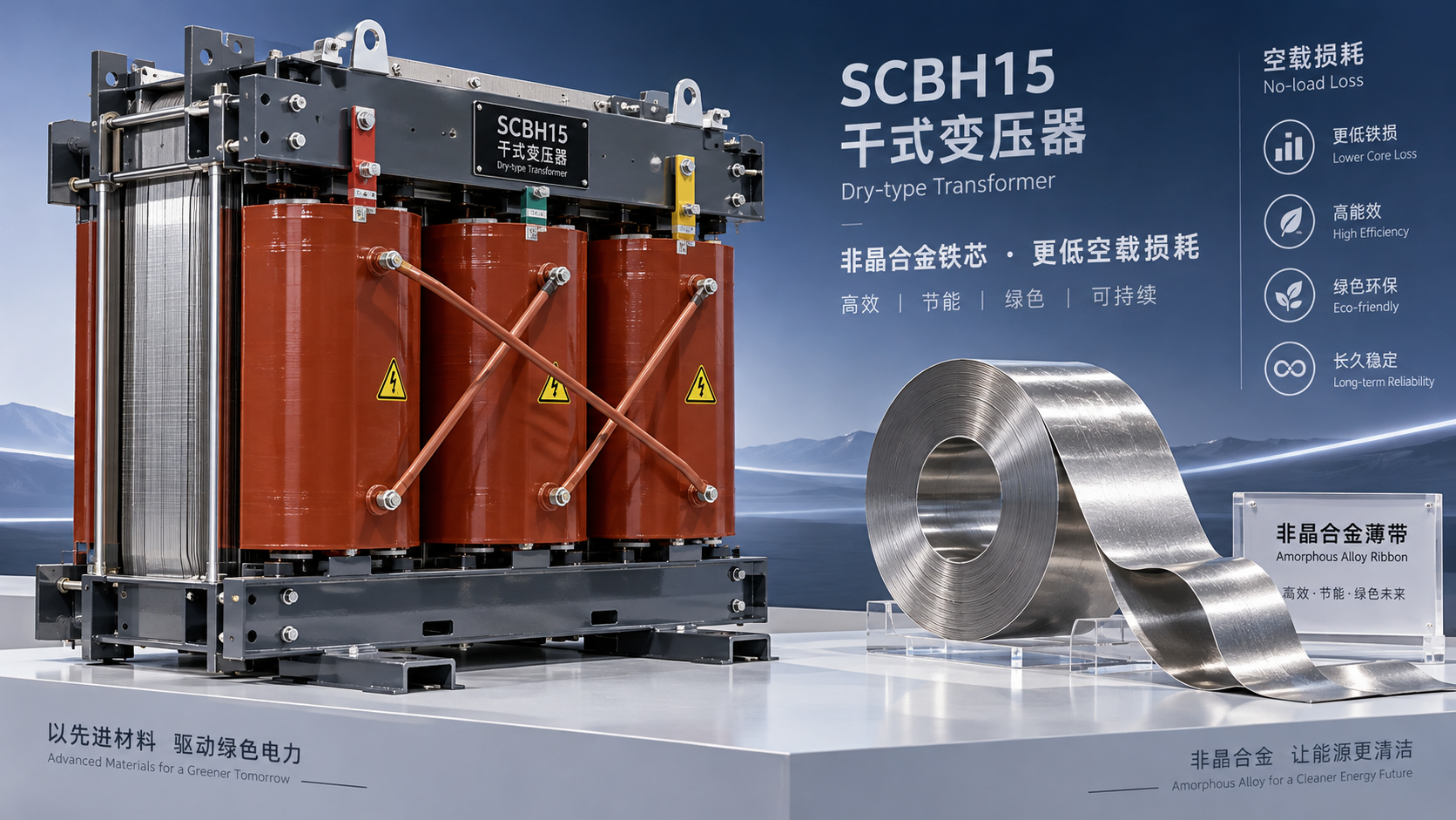
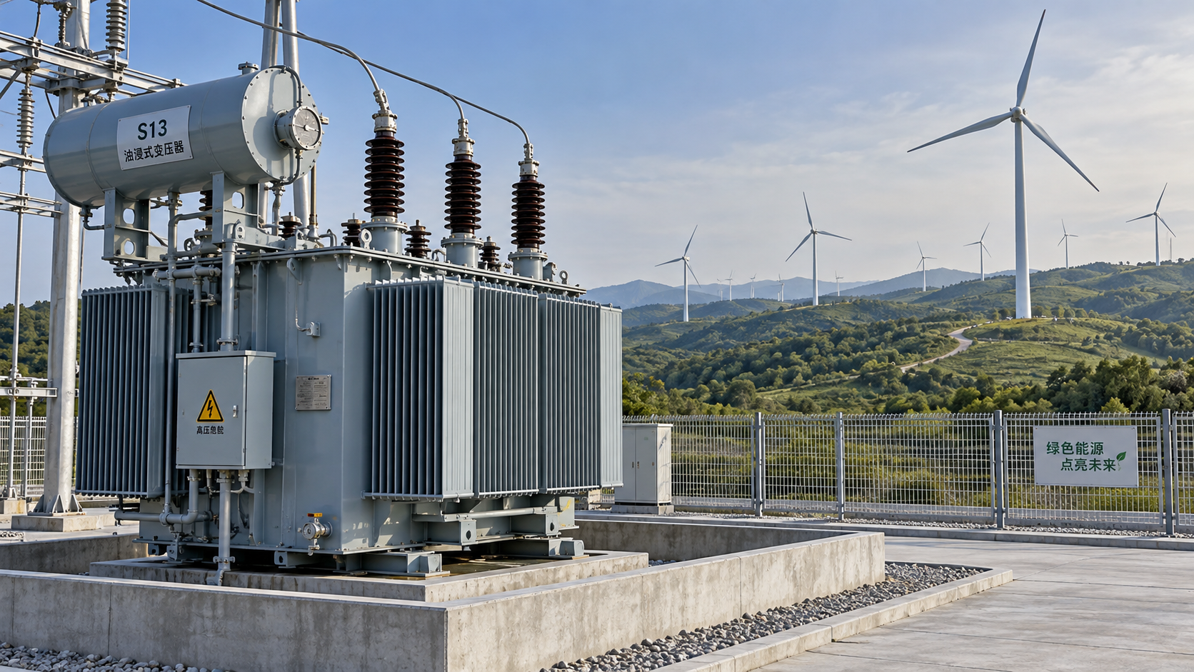
For technical evaluators, the main advantage of an SCBH15 Type Dry-Type Transformer is lower no-load loss, which can reduce electricity consumption throughout energized operating hours.
The amorphous alloy core reduces hysteresis and eddy-current losses. It does not directly reduce winding resistance, so lower total losses require a complete design comparison.
Actual performance depends on flux density, core assembly, operating temperature, voltage quality, and loading. The model designation alone cannot establish an individual unit’s efficiency or savings.
The strongest business case usually involves continuous energization with light or variable loading. At heavier loads, winding losses increasingly influence efficiency and lifecycle operating costs.
A defensible evaluation therefore combines guaranteed loss values, comparable test conditions, measured operating profiles, and installation requirements. Percentage claims without these details provide limited purchasing guidance.
Why does an amorphous core reduce no-load losses?
No-load loss is the active power consumed when a transformer operates at rated voltage and frequency with its secondary open. Most originates in the core.
Hysteresis loss occurs as alternating magnetic flux repeatedly reverses magnetization. Amorphous alloys have favorable magnetic properties that reduce the energy dissipated during each reversal cycle.
Their disordered atomic structure supports low coercivity when composition, processing, and annealing are properly controlled. These characteristics help lower hysteresis loss relative to conventional silicon steel.
Eddy currents circulate within conductive core material under alternating flux. The high electrical resistivity and thin ribbons of amorphous alloy help limit these circulating currents.
Together, these properties can produce substantially lower core losses. However, material performance measured on a sample does not automatically equal the losses of an assembled transformer.
Core joints, ribbon handling, mechanical stress, and assembly geometry affect finished performance. Evaluators should prioritize guaranteed transformer measurements over generalized comparisons between raw magnetic materials.
Which losses remain, and when do they matter most?
Load loss includes winding resistance losses and additional losses caused by leakage flux. These depend on conductor selection, winding geometry, temperature, and other design details.
An amorphous core does not inherently lower these losses. Differences in core dimensions and winding arrangements may influence them indirectly, making complete transformer data essential.
For approximately sinusoidal current, total losses can be estimated as Ptotal ≈ P0 + k²Pk + Paux, with load loss referenced to a stated temperature.
Here, P0 represents no-load loss, Pk represents rated load loss, k represents the actual load fraction, and Paux covers fans or other included auxiliary equipment.
At 30% loading, the simplified load-loss component is approximately 9% of its rated value. Under these conditions, reducing no-load loss can substantially improve overall efficiency.
As loading approaches rated capacity, load losses become more significant. Compare both loss components before assuming that an amorphous design always delivers the lowest operating consumption.
Which design and operating conditions can weaken the advantage?
Flux density deserves attention because core loss responds strongly to magnetic excitation. Excessive operating flux can increase losses, magnetizing current, and the risk of saturation.
For a given winding and core configuration, flux density approximately follows the voltage-to-frequency ratio. Overvoltage or reduced frequency can therefore move operation beyond intended conditions.
Amorphous material generally has a lower saturation flux density than conventional electrical steel. Designs must accommodate this characteristic through appropriate core dimensions, turns, and operating margins.
Core stress also matters. Cutting, bending, clamping, and inadequate handling can degrade magnetic performance, while suitable annealing and assembly practices help preserve the material’s advantages.
Operating temperature changes winding resistance and therefore load loss. Comparisons must use the same reference temperature and consider the temperature rise expected under actual loading.
Harmonic currents can increase winding eddy-current and other additional losses. Sites supplying drives, rectifiers, or extensive electronic loads need assessment beyond the simple square-law approximation.
Noise requires separate verification because amorphous materials exhibit magnetostriction, and assembly influences vibration. Lower no-load loss does not automatically guarantee a quieter transformer in service.
What test data should technical evaluators request?
Start with guaranteed no-load and load losses for the exact offered rating. Request the corresponding test report, measurement conditions, reference temperature, and applicable acceptance tolerances.
Compare units with matching rated power, voltage ratio, frequency, impedance, and cooling arrangement. Different ratings or thermal designs can make headline loss comparisons misleading.
Confirm the tap position used for testing and whether losses are guaranteed at the principal tap only. Operational tap settings may affect the relevant comparison.
No-load current is useful supporting evidence, but it differs from active no-load power loss. Do not substitute magnetizing current percentages for measured losses in watts.
Ask how the manufacturer measures low-power-factor no-load losses and addresses instrument accuracy. Measurement uncertainty becomes especially relevant when comparing transformers with small absolute core losses.
Review temperature-rise, dielectric, and sound-level results alongside efficiency data. For short-circuit withstand, request appropriate evidence demonstrating compliance with the requirements applicable to the proposed design.
Use the contractually applicable editions of transformer and efficiency standards. Older standards listed in company literature should not substitute for confirmation of current project requirements.
How can you translate lower losses into lifecycle savings?
Calculate annual energy losses by multiplying no-load loss by energized hours, then adding load losses across representative operating intervals. Include auxiliary consumption where relevant.
Use the average of squared load fractions for variable loading. Squaring the average load instead can underestimate annual load losses when demand fluctuates substantially.
Consider an illustrative comparison: one transformer has 1.5 kW no-load loss, while another has 0.5 kW. Both have 10 kW rated load loss.
At a constant 30% load, each has approximately 0.9 kW load loss. Their estimated total losses are therefore 2.4 kW and 1.4 kW, respectively.
With continuous energization for 8,760 hours, the difference equals 8,760 kWh annually. These assumed values illustrate the calculation; they are not guaranteed SCBH15 product specifications.
At an electricity price of USD 0.12 per kWh, annual savings would be approximately USD 1,051. A USD 4,000 premium implies roughly 3.8 years’ simple payback.
If rated load losses differ, include that difference at each load interval. Higher load loss can offset some core-loss savings, particularly during sustained heavy loading.
For investment approval, extend the calculation to discounted lifecycle cost using the project’s service life and discount rate. Examine tariff changes and loading uncertainty through sensitivity analysis.
How should an SCBH15 unit compare with other dry-type options?
For the SCBH15 Type Dry-Type Transformer, prioritize applications with long energized periods and substantial time below rated load. These conditions increase the value of lower core losses.
Conventional dry-type alternatives still merit evaluation where purchase price, footprint, acoustics, or delivery constraints dominate. Their suitability depends on documented performance within the same installation requirements.
Jiangsu Shengda Power Equipment Co., Ltd. develops and manufactures dry-type and amorphous alloy transformers. Request project-specific technical schedules to compare the available designs consistently.
One option is its SCB14 Type Dry-Type Transformer, described as an epoxy-resin design with level 2 energy efficiency under GB20052-2020 and low-noise operation.
Its stated applications include high-rise buildings, airports, railway stations, and substations. Verify the offered rating’s certified losses, acoustic data, and installation conditions before selecting it.
For locations with demanding fire requirements, check enclosure, ventilation, fire classification, and applicable approvals. Flame-retardant insulation alone does not establish suitability for explosive atmospheres.
What should determine the final selection?
The amorphous core primarily improves the continuously incurred no-load component. Its practical value depends on energized hours, loading distribution, electricity prices, and the transformer’s complete loss profile.
Select the unit that combines verified losses with acceptable thermal performance, noise, dimensions, and lifecycle cost. Treat the core material as an advantage requiring measurable confirmation.
A sound purchasing decision rests on comparable guarantees and realistic operating data. That approach turns a promising efficiency claim into an auditable engineering and financial conclusion.