


A temperature-rise test for an SCB12 Type Dry-Type Transformer is acceptable only when the measured winding rise can be traced to the specified rating, cooling arrangement, test method, and insulation-system limit. A final temperature reading alone cannot establish compliance. The report must connect the electrical loading and surrounding air temperature to the winding temperature calculated at the end of a valid, thermally stabilized test.
Begin with the transformer specification and the agreed acceptance criteria. The SCB12 designation identifies a product series; it does not establish the permissible winding temperature rise, conductor material, or cooling rating. Those details must come from the nameplate, approved technical documents, and applicable dry-type transformer standard.
Establish the basis for the acceptance limit
The report should identify the governing standard and edition, together with any contractual requirements that modify the test conditions or acceptance limits. A reference to a general transformer standard without the relevant dry-type thermal requirements leaves the basis for acceptance incomplete. Older standard references in a catalogue also do not establish which edition governs a particular order.
Separate the insulation system’s thermal class from the permitted average winding temperature rise. Thermal class concerns the temperature capability of the insulation system; the acceptance limit for a resistance-based test concerns average winding rise under specified conditions. Treating the thermal-class temperature as an allowable rise creates an incorrect acceptance threshold.
The documented basis should distinguish:
- Rated operation: the power rating, frequency, tap position, and cooling mode represented by the test.
- Thermal requirements: the declared insulation system and the applicable winding-rise limit, including different limits where winding systems differ.
- Service conditions: specified ambient temperature and altitude. Unusual conditions require the treatment defined in the governing documents.
Temperature rise is a temperature difference, commonly expressed in kelvins. Its numerical value equals the corresponding difference in degrees Celsius, but it must remain distinguishable from an absolute winding temperature.
Match the tested configuration to the declared rating
Natural-air and forced-air ratings represent different cooling conditions. A test conducted with fans running supports the rating associated with that fan arrangement. It cannot establish compliance at a natural-air rating unless the specified procedure separately demonstrates that condition.
Record fan status, supply conditions, airflow direction, and control behavior throughout the test. Automatic fan switching changes heat removal, so an undocumented switching event makes the temperature trend difficult to interpret. Temporary laboratory fans or airflow directed toward the coils also alter the cooling conditions.
The enclosure matters because it changes the air path. Compare the tested enclosure, ventilation openings, and clearances with the configuration covered by the report. A bare transformer test does not automatically establish the thermal performance of an enclosed installation. Nearby walls, restricted lower air inlets, and obstructed upper outlets can increase winding temperature even when electrical loading is unchanged.
This distinction also applies when comparing the epoxy-resin construction of an SCB14 Type Dry-Type Transformer with an SCB12 design. Reduced no-load loss changes part of the heat generated, but thermal acceptance still depends on load loss, winding geometry, ventilation, and the tested rating. A series designation or efficiency claim cannot substitute for temperature-rise evidence.
Confirm that the heating method represents the required losses
Identify whether the test used direct loading, a back-to-back arrangement, or another method permitted by the governing standard. Different methods establish the required heating conditions in different ways. The report must show how the selected procedure represents both winding-related losses and core-related heating, including any prescribed combination of test stages.
Rated current alone is insufficient evidence. A short-circuit heating arrangement produces winding losses while the applied voltage is much lower than rated voltage, so core heating differs from normal service. Where this arrangement forms part of an accepted method, the additional measurements and calculation required by that method must be documented.
Review recorded current, voltage, frequency, and power against the intended conditions. Current imbalance produces unequal phase heating. An incorrect frequency or excitation condition changes core loss. Tap position also affects the electrical conditions, and the report must justify the selected tap against the specified test requirement.
Any correction for departures from target current or losses should follow the applicable procedure. An unexplained adjustment that turns a failing measured result into a passing reported value requires examination of the original readings and correction basis.
Use ambient measurements that represent incoming cooling air
Ambient sensors should measure the air surrounding and entering the transformer’s cooling path, using the positions and shielding required by the test procedure. A sensor exposed to hot exhaust air overstates ambient temperature and understates the calculated winding rise. A sensor beside a cold supply-air jet creates the opposite distortion.
Retain the individual ambient readings and the method used to derive the reference temperature. A single room thermometer cannot demonstrate whether the air around the transformer was uniform. Sensor positions, calibration status, and protection from radiant heat belong in the test record.
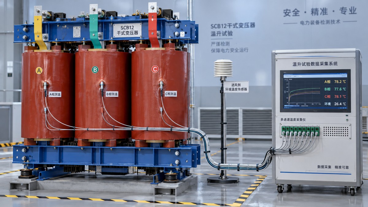
Plot ambient temperature alongside winding indicators and electrical loading. A nearly constant winding temperature during a falling room temperature can conceal an increasing temperature rise. Likewise, an apparent plateau produced by reducing current does not demonstrate stabilization at the required load.
Thermal stabilization must satisfy the criterion in the applicable standard, using the required observation interval and temperature trend. Elapsed test time alone is insufficient. Cast-resin windings retain heat, and surface sensors can respond differently from the average conductor temperature determined by resistance.
Reconstruct the winding temperature from resistance measurements
The resistance method links conductor resistance to average winding temperature. Its reliability depends on an accurate cold reference, prompt hot measurements after shutdown, and correct treatment of cooling during measurement.
Before heating, the reference winding temperature must be established under the conditions required by the procedure. If the winding has not reached thermal equilibrium, assigning room temperature to the cold resistance introduces an error into every subsequent calculation.
A general form of the resistance-temperature relationship is:
θhot = (Rhot / Rcold) × (K + θcold) − K
Here, Rcold and Rhot are resistances for the same winding measurement path, θcold is its reference temperature, and K is the material constant specified for the conductor. Copper and aluminium require different constants. The report must identify the conductor material rather than infer it from the model name.
After shutdown, winding temperature starts falling. Record the shutdown time, measurement times, resistance readings, and measurement sequence. Where required, derive the resistance at shutdown through the prescribed extrapolation procedure. Using a delayed reading without the required treatment understates the end-of-test temperature.
Calculate rise by subtracting the prescribed ambient reference from the calculated winding temperature. Repeat the evaluation for each required winding and phase. Preserve the highest applicable result; averaging phases can conceal an individual exceedance.
Interpret sensor readings and issue a defensible result
An embedded temperature detector measures temperature at its installed location. Resistance measures average conductor temperature over the measurement path. These values need not agree, and neither directly establishes the hottest point without an accepted relationship or supporting method.
A low detector reading therefore cannot override an excessive resistance-based rise. Conversely, an unusually high detector reading deserves investigation of its location, contact, wiring, and local cooling conditions. Infrared surface measurements are useful for locating uneven heating, but emissivity and surface temperature limit their use as substitutes for the specified acceptance measurement.
The final report should preserve equipment identification, configuration records, instrument calibration details, loading history, ambient trends, stabilization evidence, resistance data, calculations, and the applicable limits. Any reliance on a previous design test needs a documented basis showing that the tested design represents the transformer under assessment, including thermally significant differences.
Record the result separately for each required rating and cooling mode. An exceedance under valid conditions is a failed result; missing stabilization evidence or unusable shutdown measurements leave compliance unproven. Retesting should address the specific gap so that the replacement result supports a clear acceptance decision.



 How to verify the temperature-rise test of an SCB12 dry-type transformer
 Distribution transformer maintenance tips for spotting oil leaks
 What dissolved gas analysis reveals about an oil-immersed transformer
 Why an oil-cooled transformer overheats despite a normal oil level
 How the amorphous core affects SCBH15 dry-type transformer losses
 Sizing S13 oil-immersed transformers for variable wind farm output
GET A FREE QUOTE
We offer reliable products, competitive prices, and nationwide professional support, committed to providing customers with efficient and energy-saving power equipment solutions.