


When Does the S13 Transformer Actually Deliver Grid Code Compliance—Not Just Efficiency?
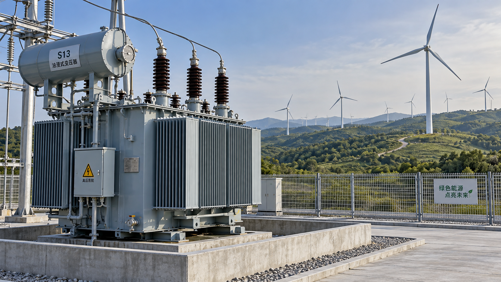
For project managers deploying wind or solar farms, selecting a transformer isn’t about picking the lowest-loss unit on paper. It’s about whether that unit can *hold up* under grid code enforcement—especially when reactive power support and harmonic mitigation are triggered by real-time voltage dips, rapid generation fluctuations, or converter switching events. The S13 Series Oil-Immersed Power Transformer is frequently specified for renewable energy projects—but its compliance value depends entirely on *how* it interfaces with the rest of the system—not just its no-load loss rating.
Reactive Power Support: Why Core Design Matters More Than Tap-Changer Specs
Grid codes (e.g., ENTSO-E RfG, China’s GB/T 19964, or IEEE 1547-2018) require inverters—and increasingly, transformers—to contribute to voltage stability via reactive power injection or absorption during faults or transients. But here’s what’s often overlooked: a transformer’s ability to respond reliably isn’t determined by its tap changer alone. It hinges on magnetic core integrity under dynamic load cycles.
The S13’s cold-rolled grain-oriented silicon steel core, with optimized lamination stacking and reduced joint air gaps, minimizes flux leakage and hysteresis distortion during rapid VAR swings. This means less risk of saturation-induced harmonics when the inverter commands +0.95/-0.95 pu reactive power within 20 ms—conditions where older S9 or even some S11 units show delayed response or localized heating at limb joints. Crucially, this design also improves the consistency of on-load tap-changer (OLTC) operation under unbalanced reactive demand—a common stressor in distributed solar plants feeding into radial feeders.
That said, OLTC specification remains non-negotiable. An S13 without IEC 60216-compliant insulation coordination for frequent tap transitions—or without integrated monitoring for tap position drift under harmonic-rich loads—won’t sustain compliance over time. Verify that the unit includes real-time thermal modeling of winding hot spots during combined active/reactive loading, not just steady-state ratings.
Harmonic Mitigation: Not About “Blocking,” But About Containing and Damping
Renewable plants generate harmonics primarily from power electronics—not the transformer itself. So expecting an S13 to “filter” harmonics is a fundamental misalignment. Its role is containment: preventing harmonic currents from amplifying resonance, overheating windings, or distorting voltage waveforms beyond grid code thresholds (e.g., <5% THDV at PCC per GB/T 14549).
The S13 achieves this through three interdependent features: (1) low zero-sequence impedance (enabled by three-limb core construction), which limits triplen harmonic circulation; (2) high short-circuit impedance tolerance (typically 6–8% for 35 kV units), providing inherent damping against parallel resonance with capacitor banks; and (3) robust oil-paper insulation systems rated for continuous 3rd/5th/7th harmonic voltage superposition—verified per GB/T 6451-2008 Annex E.
But be cautious: a low-loss S13 with ultra-thin insulation layers may meet efficiency standards while failing long-term dielectric endurance under harmonic stress. Confirm that partial discharge inception voltage (PDIV) is tested at 1.5× fundamental + 0.3× 5th harmonic voltage—not just sinusoidal AC. That test separates compliant units from those optimized only for no-load loss reduction.
Where Dry-Type Alternatives Fit—and Where They Don’t
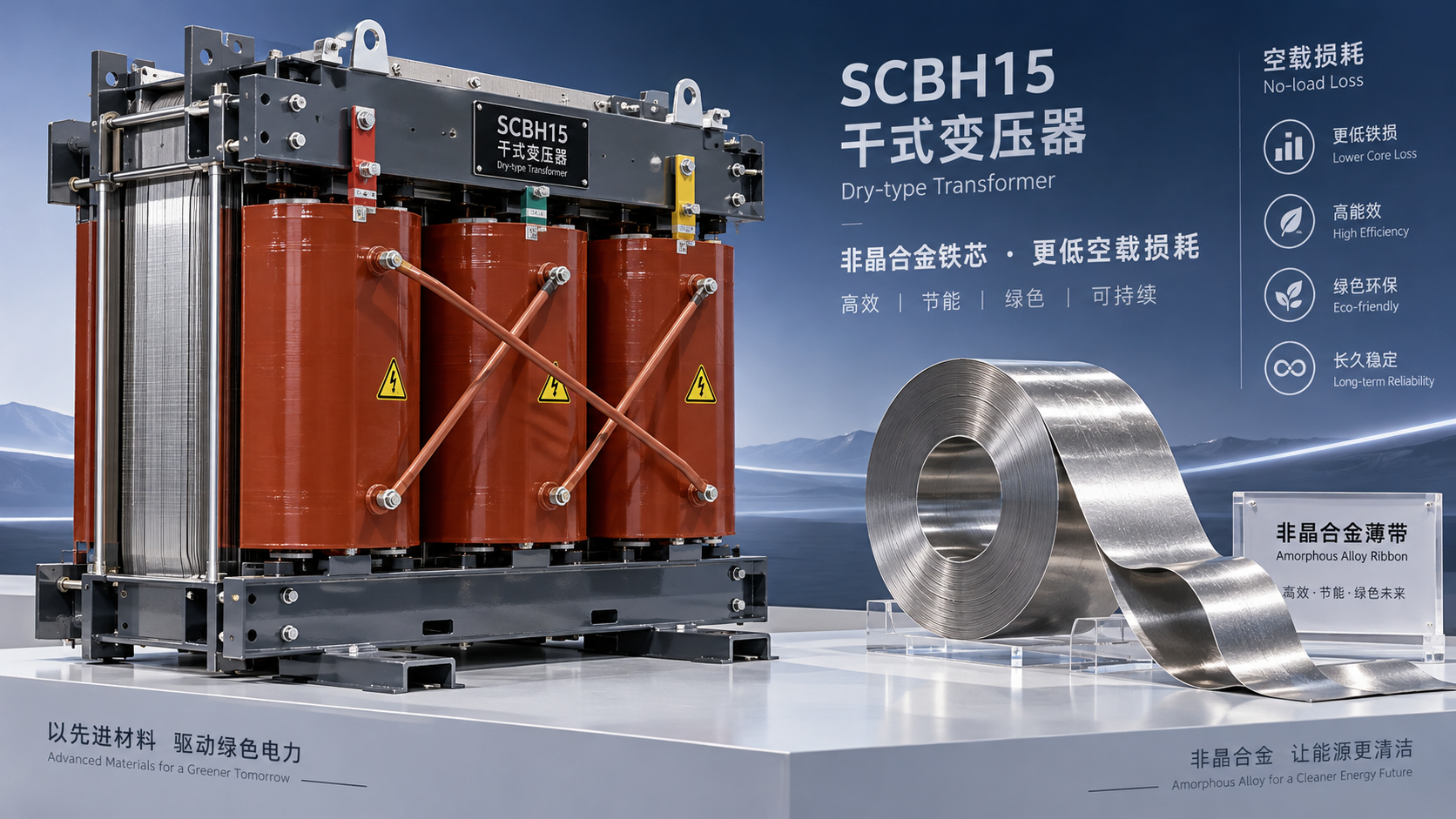
In certain substation configurations—especially indoor switchgear rooms adjacent to control centers or fire-sensitive zones—dry-type units offer distinct advantages. Their flame-retardant epoxy resin insulation, moisture resistance, and absence of flammable oil eliminate explosion and spill risks. For these applications, the SCB14 Type Dry-Type Transformer delivers level 2 efficiency per GB20052-2020, low noise, and high short-circuit withstand—making it suitable where proximity to personnel or critical infrastructure demands passive fire safety.
Yet dry-types introduce trade-offs for grid code compliance: higher leakage reactance (often 6–10%) increases harmonic voltage distortion at the point of common coupling, requiring tighter coordination with active filters. Their lower thermal mass also limits overload capability during fault ride-through—critical when reactive support must be sustained for 150 ms or longer. For primary collection substations feeding directly into transmission networks, oil-immersed S13 remains the more predictable platform for meeting strict harmonic and reactive power mandates.
Compliance Isn’t Static—It’s Validated in Context
A certified S13 unit meeting GB1094.1-2-1996 and GB/T6451-2008 is necessary—but insufficient. Real-world compliance emerges only when the transformer is modeled *with* the plant’s specific inverter characteristics, cable impedances, and protection relay settings. We’ve seen cases where identical S13 units passed factory tests but failed site commissioning due to resonant interactions between OLTC step size and inverter control loop bandwidth.
Before finalizing procurement, insist on system-level harmonic analysis (IEEE 519-2022 methodology) using the actual transformer’s measured impedance matrix—not generic catalog values. Likewise, require reactive power step-response validation under simulated grid faults—not just nameplate VAR range. These aren’t optional extras; they’re the only way to confirm the S13 will perform as a stable, compliant interface—not just an efficient component.
Ultimately, the S13’s value lies not in its efficiency label, but in how its physical design tolerates the electrical violence of modern renewables integration. Choose it when you need predictable, field-proven behavior under transient stress—not just a lower kWh loss on the balance sheet.



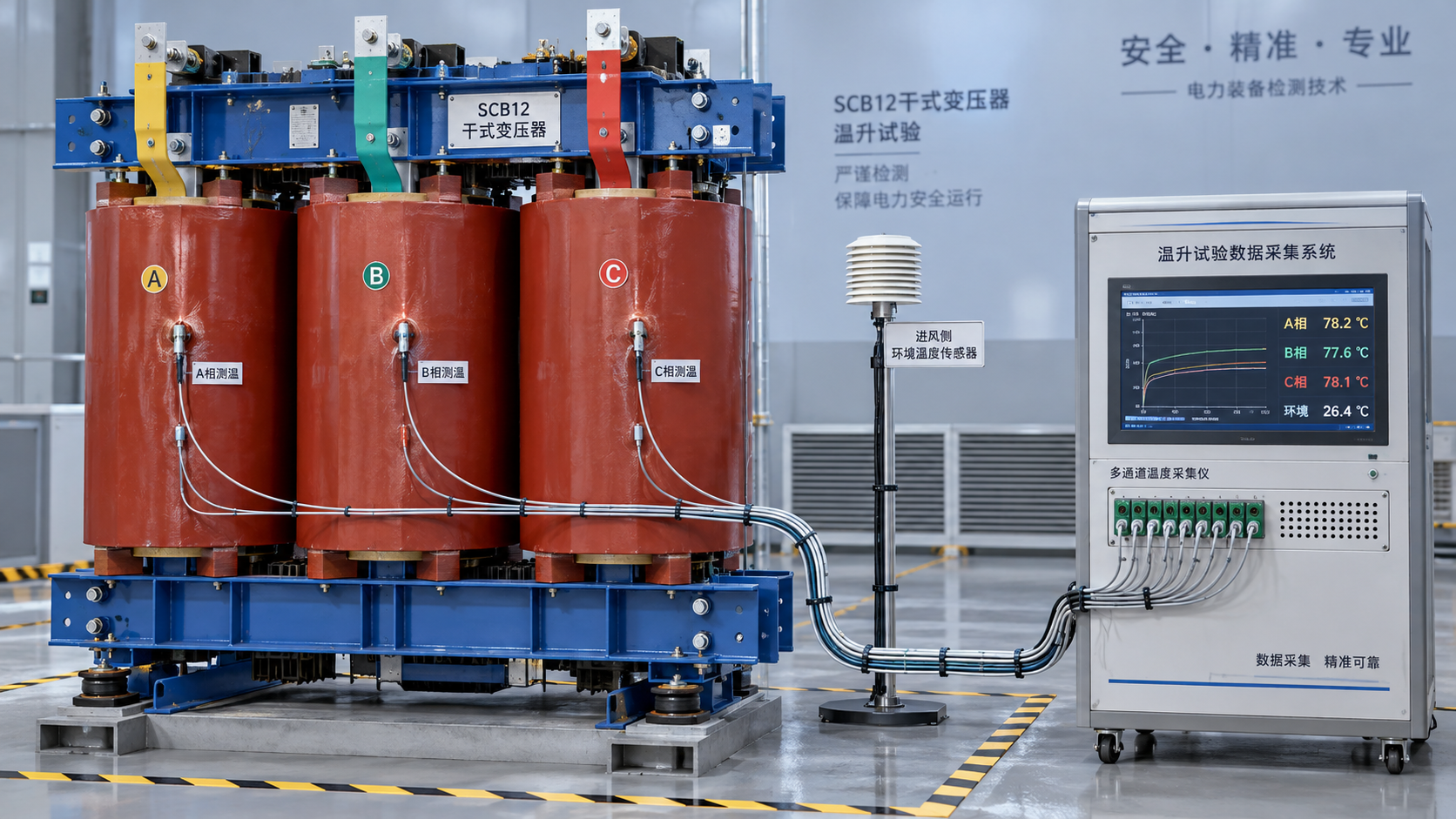
 How to verify the temperature-rise test of an SCB12 dry-type transformer
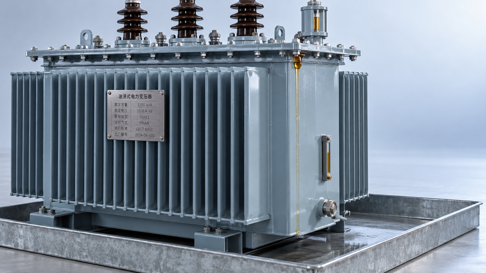
 Distribution transformer maintenance tips for spotting oil leaks
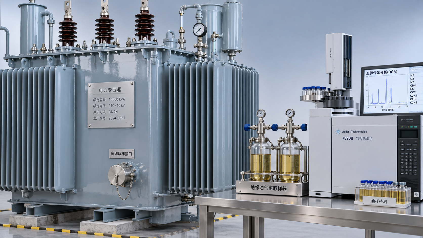
 What dissolved gas analysis reveals about an oil-immersed transformer
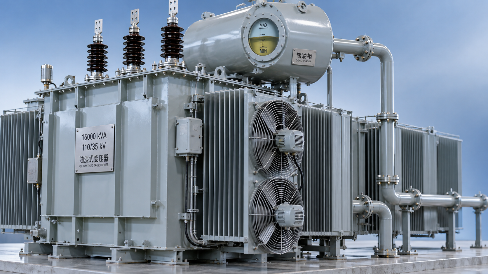
 Why an oil-cooled transformer overheats despite a normal oil level
 How the amorphous core affects SCBH15 dry-type transformer losses
 Sizing S13 oil-immersed transformers for variable wind farm output
GET A FREE QUOTE
We offer reliable products, competitive prices, and nationwide professional support, committed to providing customers with efficient and energy-saving power equipment solutions.