


Sizing S13 oil-immersed transformers for variable wind farm output
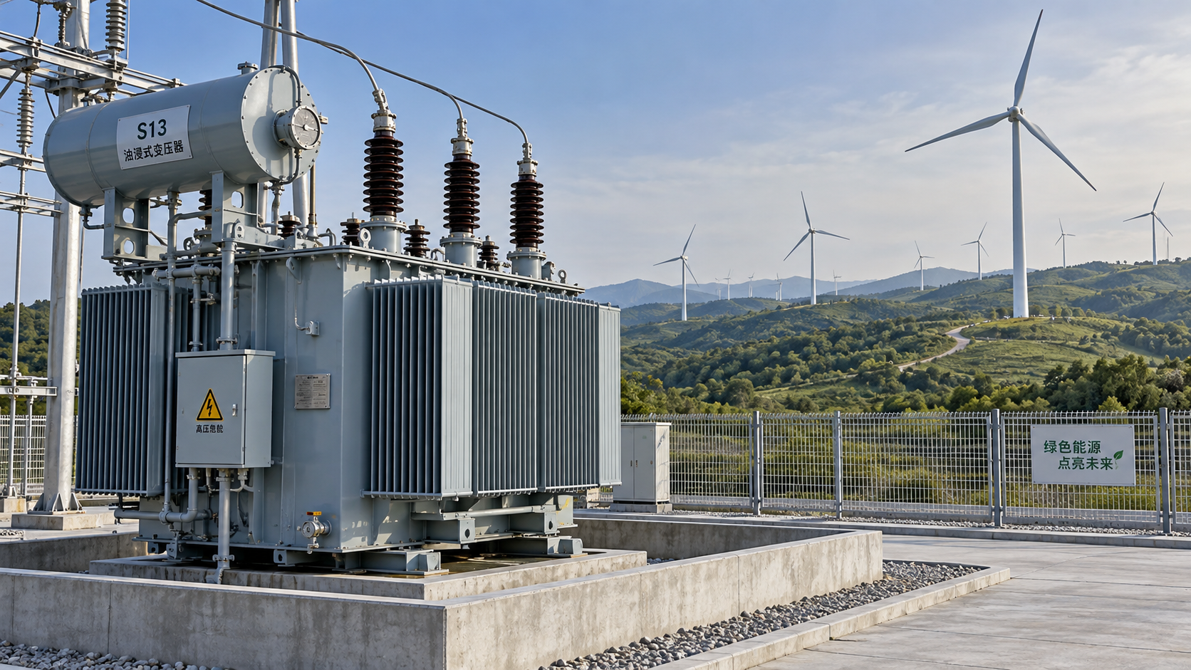
Variable wind generation makes transformer sizing more complex than matching a nameplate rating to installed turbine capacity. Selecting an S13 Series Oil-Immersed Power Transformer for wind farms means balancing peak power transfer, fluctuating loads, thermal limits, and lifecycle losses without oversizing the investment. Generation profiles, reactive power requirements, site conditions, and grid connection specifications all shape the decision. Once these are defined, engineering teams can evaluate suppliers such as Jiangsu Shengda Power Equipment Co., Ltd. against a project-specific specification rather than a series designation alone.
Define which part of the wind farm the transformer serves
A turbine step-up transformer, a collector feeder transformer, and the main grid-export transformer face different duties. The turbine unit must suit the generator or converter output voltage and its operating envelope. A collector transformer carries the combined output of its connected turbines. The main export transformer must accommodate the collector network and grid interface, often at a different voltage and capacity scale.
That distinction matters before selecting an S13 model. The designation does not establish compatibility with converter waveforms, required voltage ratios, or every wind-farm capacity. Confirm the actual winding arrangement, rated voltages, cooling method, and available power rating. A catalogue covering 10 kV and 35 kV equipment does not automatically cover a higher-voltage export connection.
Also define the power-flow boundary. An export cap at the grid connection may reduce downstream transfer, but it does not necessarily limit every upstream transformer. The electrical layout and curtailment controls must demonstrate where that limit applies.
Size for apparent power, not average generation
Wind-farm capacity factor describes energy production over time; it is not a transformer sizing multiplier. A farm with modest annual average output can still operate near full power for extended periods. Nearby turbines may experience similar wind conditions, so assumed diversity needs evidence from site-specific generation studies.
The electrical starting point is apparent power: S = √(P² + Q²), where P is active power and Q is reactive power at the transformer terminals. Where a defined power factor applies, S = P / power factor. Check simultaneous active and reactive requirements rather than combining unrelated maxima.
For illustration only, transferring 2 MW at a power factor of 0.95 requires approximately 2.11 MVA before site derating or other design allowances. This is a calculation example, not a recommended transformer rating. The selected unit still needs to satisfy voltage variation, harmonic heating, and the agreed thermal duty.
Reactive support may also be required during low wind output. Establish whether turbine converters, separate compensation equipment, or both provide it, and identify which transformer carries that current. Low MW output does not always mean low transformer loading.
Use a chronological load profile to check thermal limits
A load-duration curve helps estimate losses, but it cannot show whether high-output hours occur consecutively. Thermal assessment needs a chronological profile because winding hot-spot and oil temperatures depend on previous loading as well as current loading.
Provide the manufacturer with time-series active and reactive power, ambient temperatures, expected operating voltage, and cooling availability. Ask for a loading assessment against the applicable IEC 60076-7 or corresponding project standard. The assessment should state its assumptions, temperature limits, and implications for insulation ageing.
Plotting transformer apparent power alongside ambient temperature and predicted hot-spot temperature makes sustained high-load periods easier to identify.
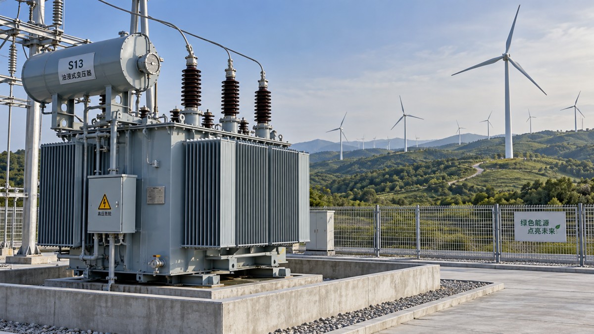
Do not treat overload capability as free continuous capacity. Any overload allowance should have defined duration, starting temperature, cooling conditions, and operational controls. If the project depends on curtailment to protect the transformer, that dependence belongs in the control specification and operating agreement.
Resolve site and grid constraints before freezing the rating
Higher altitude, elevated ambient temperature, or restricted airflow around a compact substation can reduce usable thermal capacity. Coastal contamination, corrosion exposure, and low-temperature operation create additional design requirements, even when they do not directly change the nominal MVA rating.
- Converter harmonics: request the expected current spectrum and assess additional winding and stray losses. A low-loss designation is not proof of harmonic suitability.
- Impedance and fault duty: coordinate short-circuit impedance with voltage regulation, protection settings, and network fault levels. Confirm short-circuit withstand requirements separately.
- Voltage control: establish tap range and whether off-circuit adjustment is sufficient. An on-load tap changer should follow the voltage-control study, not be added by habit.
- Insulation and earthing: specify insulation levels, vector group, neutral arrangement, and surge protection from the collector-system design.
Oil containment, fire separation, access, and transport limits also need early review. A transformer that fits electrically but requires a late foundation or enclosure redesign can disrupt the project schedule.
Compare losses over the operating profile
An oversized transformer offers headroom, but may carry greater no-load losses and capital cost. An undersized unit can create thermal restrictions or force generation curtailment. Compare candidate ratings using annual loss energy and operational constraints rather than purchase price alone.
For a preliminary calculation, losses can be estimated as P₀ + Pk × x², where P₀ is no-load loss, Pk is rated load loss, and x is per-unit loading. Apply this across the load profile, allowing for energized hours. Detailed evaluation should account for temperature, harmonics, and cooling auxiliaries where relevant.
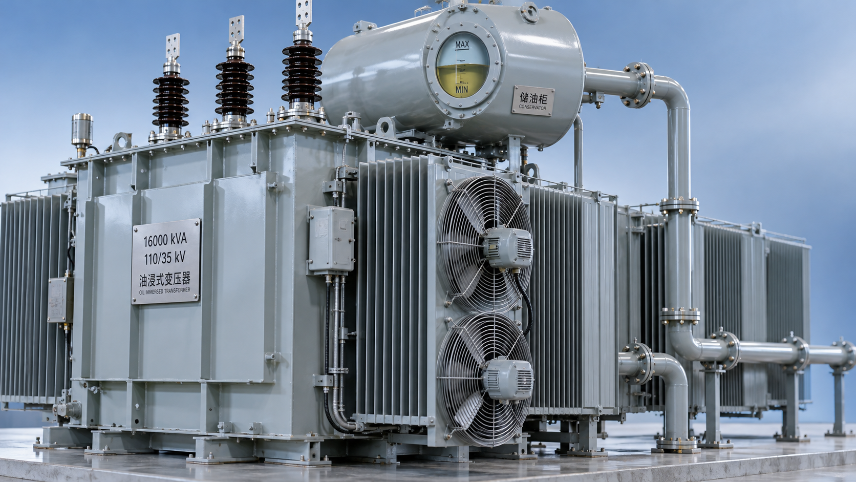
Shengda’s S11 Series Oil-Immersed Power Transformer provides a related comparison option, with listed ratings from 30 to 2,500 kVA and a fully sealed corrugated-tank design. Its specified cold-rolled silicon steel and oxygen-free copper are construction details, not substitutes for guaranteed loss figures. Compare it with an S13 proposal only at equivalent electrical duty and test conditions; do not transfer S11 specifications to S13 equipment.
Make supplier review specific enough to prevent substitutions
Jiangsu Shengda Power Equipment Co., Ltd. develops, manufactures, and sells transformer equipment, including S13 and other low-loss series, compact substations, dry-type transformers, and on-load tap-changing designs. This range allows discussion of both the transformer and its surrounding installation, but each offered model still needs documented suitability for the wind-farm duty.
The company states ISO9001 certification and references GB1094.1-2-1996 and GB/T6451-2008. These are Chinese standards references; confirm the editions and any additional standards required by the project. Quality-management certification does not replace product-specific test evidence.
Before approving the rating, obtain guaranteed losses, temperature-rise limits, impedance tolerances, drawings, protection interfaces, and an agreed factory test plan. Identify whether relevant type-test reports apply to the offered design and which tests will be witnessed. Freeze the transformer rating only when the electrical study, thermal assessment, site conditions, and supplier guarantees agree. If they do not, resolve the mismatch through a revised rating, cooling arrangement, or explicit operating limit—not an undocumented safety margin.



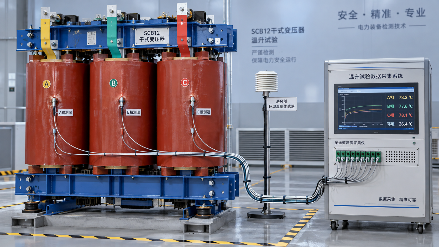
 How to verify the temperature-rise test of an SCB12 dry-type transformer
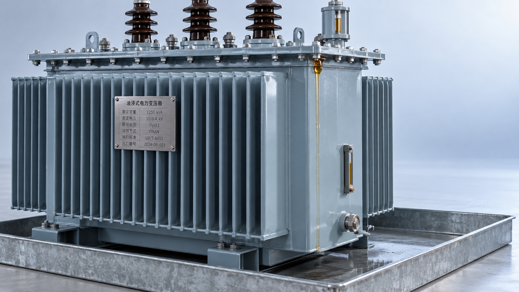
 Distribution transformer maintenance tips for spotting oil leaks
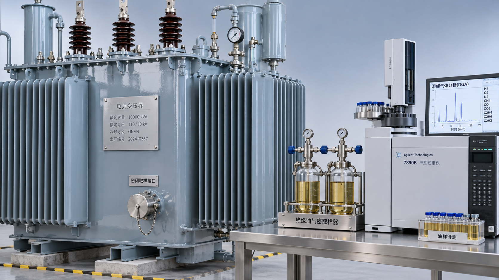
 What dissolved gas analysis reveals about an oil-immersed transformer
 Why an oil-cooled transformer overheats despite a normal oil level
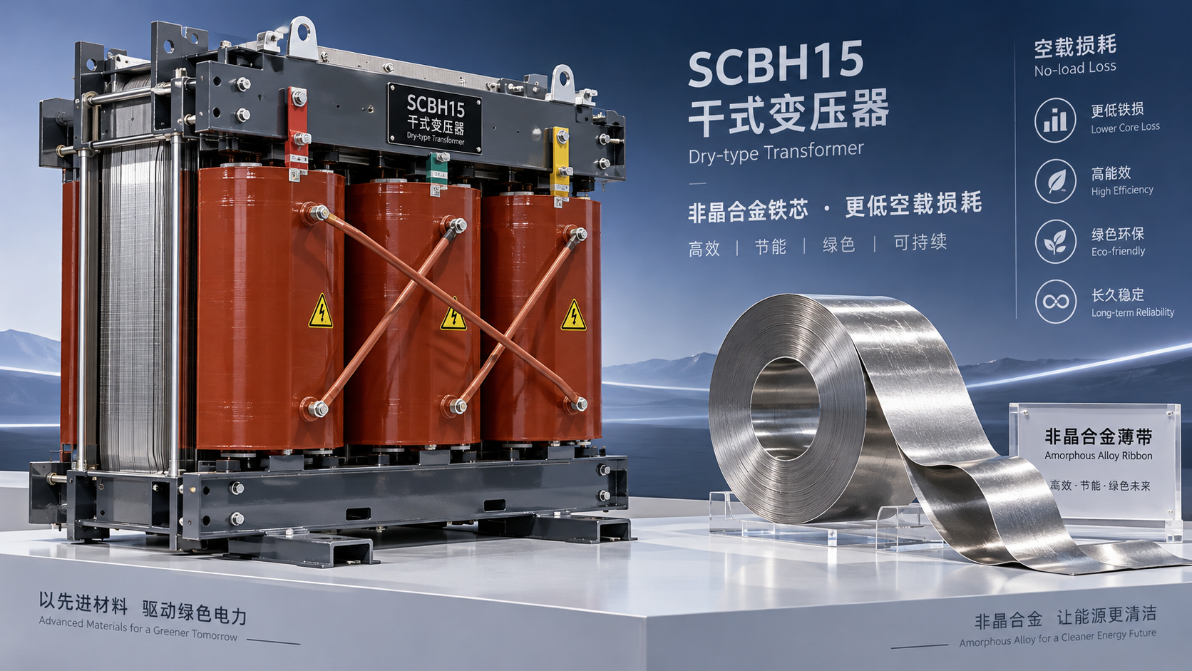
 How the amorphous core affects SCBH15 dry-type transformer losses
 Sizing S13 oil-immersed transformers for variable wind farm output
GET A FREE QUOTE
We offer reliable products, competitive prices, and nationwide professional support, committed to providing customers with efficient and energy-saving power equipment solutions.