


Why Step-Up Transformer Sizing Is the Single Most Critical Design Decision for Wind Farm Grid Integration
Selecting the right step-up transformer is not a routine specification task—it’s the linchpin of grid compliance, asset longevity, and operational ROI for wind farm projects. When stepping generator output from 690V to a 33kV collection grid, undersizing invites thermal overload and premature failure; oversizing triggers magnetizing inrush issues and reactive power imbalance; but incorrect impedance or tap range selection—especially under dynamic wind generation profiles—directly enables dangerous overvoltage transients during load rejection, fault clearance, or grid synchronization events. For project managers overseeing multi-MW onshore or offshore installations, this isn’t theoretical risk: it translates into unplanned outages, grid code noncompliance penalties, and costly retrofits post-commissioning.
What Project Managers Actually Need to Verify—Not Just “Rated kVA”
Most engineering teams default to sizing based on generator nameplate rating (e.g., 3.6 MVA for a 3.3 MW turbine at 0.95 pf). But real-world operation demands deeper scrutiny. First, confirm continuous thermal capacity—not just short-time overload capability—under worst-case ambient conditions (e.g., +45°C desert sites or humid coastal zones). Second, evaluate voltage regulation performance across the full active/reactive power operating envelope: wind turbines frequently operate at leading power factor during low-wind periods, which can cause secondary voltage rise beyond nominal limits if transformer impedance and tap-changer coordination are misaligned. Third, validate transient overvoltage suppression capability: IEEE C57.12.00 requires transformers to withstand 1.5× rated voltage for 10 seconds during system faults—but that’s meaningless without proper coordination with surge arresters, grounding design, and cable capacitance modeling.
Crucially, avoid “one-size-fits-all” assumptions about tap range. A ±10% tap changer may suffice for stable grid interconnection—but for weak grids or long collector feeders, ±12.5% or even ±15% is often mandatory to maintain voltage within EN 50160 limits during ramp-down events. Jiangsu Shengda Power Equipment engineers routinely perform harmonic and ferroresonance studies during design review to pre-empt resonance-driven overvoltages—a common root cause of insulation failure in 33kV wind farm step-up units.
The Three Non-Negotiable Technical Criteria You Must Specify Upfront
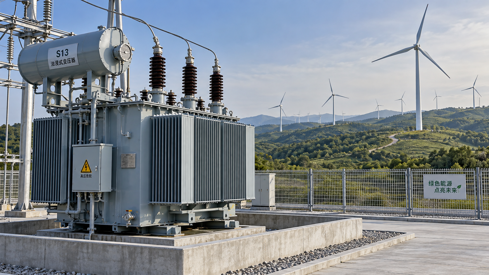
1. Impedance Matching for Transient Stability: Target 6–8% short-circuit impedance—not generic “6% ±1%”. Too low (<5.5%) amplifies fault current and stresses switchgear; too high (>8.5%) causes excessive voltage drop during turbine startup and reduces reactive power support margin. Our S13 and S20 series oil-immersed step-up transformers are optimized for this band, with precision-wound coils validated via FEM-based magnetic field simulation.
2. Tap-Changer Type & Coordination Logic: Avoid off-load tap changers for wind applications. On-load tap changers (OLTC) must be synchronized with SCADA via Modbus or IEC 61850—enabling automatic voltage regulation during rapid wind speed changes. We integrate OLTC control logic with turbine reactive power setpoints to prevent conflicting actions between turbine inverters and transformer taps.
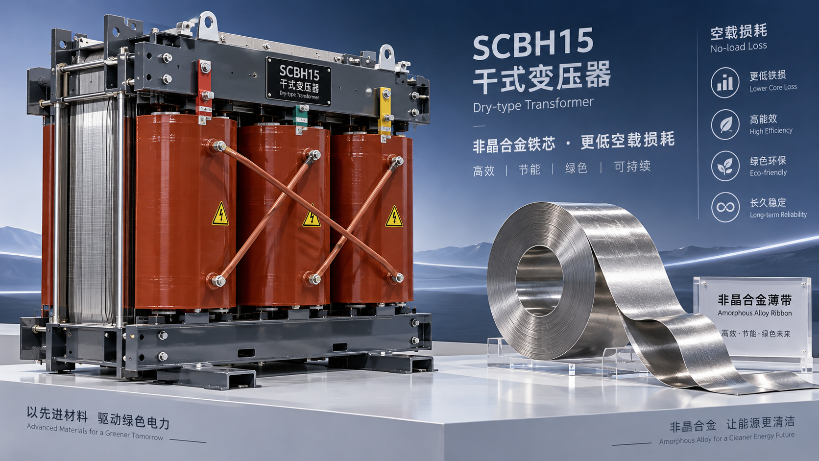
3. Insulation Coordination & Partial Discharge Performance: With fast-rising switching transients from modern converters, partial discharge (PD) inception voltage must exceed 1.7× rated phase-to-phase voltage. Our dry-type units achieve <5 pC PD level at 1.1× Um, verified per IEC 60076-3—and critical for compact substations where space constraints increase electric field stress. For demanding environments like offshore platforms or high-rise-integrated wind systems, the SCB10 Type Dry-Type Transformer delivers Class F insulation, flame-retardant epoxy resin, and dust/moisture protection—making it suitable for flammable locations where fire safety is non-negotiable.
How Jiangsu Shengda Ensures Zero-Surprise Commissioning
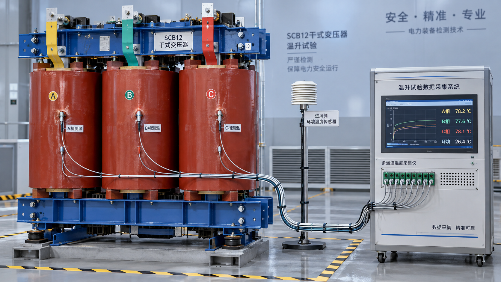
We don’t just supply transformers—we de-risk integration. Every step-up unit undergoes full-load temperature rise testing at our ISO 9001-certified facility, replicating actual wind farm duty cycles: 72-hour cyclic loading with 120% overload for 30 minutes every 4 hours, simulating gust-driven power surges. All units comply strictly with GB1094.1-2-1996 (equivalent to IEC 60076-1/2) and GB/T6451-2008, with third-party verification by China Quality Certification Center (CQC). Crucially, we deliver not just test reports—but coordinated protection settings: relay pickup values, CT ratios, and arc-flash hazard analysis aligned with your 33kV switchgear manufacturer’s specifications.
For project managers managing tight EPC timelines, our modular design approach enables factory-assembled, pre-tested compact substations—including integrated metering, protection relays, and remote monitoring interfaces—reducing on-site commissioning time by up to 40%. And because wind farm O&M budgets hinge on reliability, our S15 and S22 low-loss series reduce no-load losses by up to 25% versus legacy designs—translating directly into lower lifetime energy costs and faster payback.
Final Recommendation: Treat Transformer Sizing as a System-Level Engineering Task
Never treat the step-up transformer as an isolated component. Its sizing, specification, and testing must be co-developed with turbine OEMs, grid operator requirements, cable routing plans, and protection philosophy. Start early: engage transformer specialists during FEED phase—not procurement. Demand transient modeling reports—not just datasheets. Verify that the supplier provides not only compliance certificates, but also application-specific validation: ferroresonance studies, harmonic distortion analysis at PCC, and coordinated voltage control logic diagrams. At Jiangsu Shengda, we embed these deliverables into our standard scope—because for project managers, the cost of a wrong transformer decision isn’t measured in dollars, but in months of delayed revenue and reputational risk.
In summary: precise step-up transformer sizing for 690V-to-33kV wind integration hinges on three pillars—thermal resilience under variable load, impedance-tap coordination for transient stability, and insulation robustness against converter-induced surges. When those are engineered rigorously—and backed by ISO-certified manufacturing and application-specific validation—you eliminate overvoltage transients before they occur. That’s not just compliance. It’s confidence.



 How to verify the temperature-rise test of an SCB12 dry-type transformer
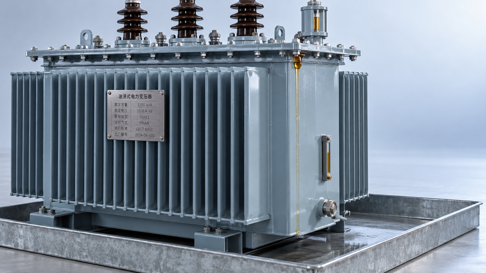
 Distribution transformer maintenance tips for spotting oil leaks
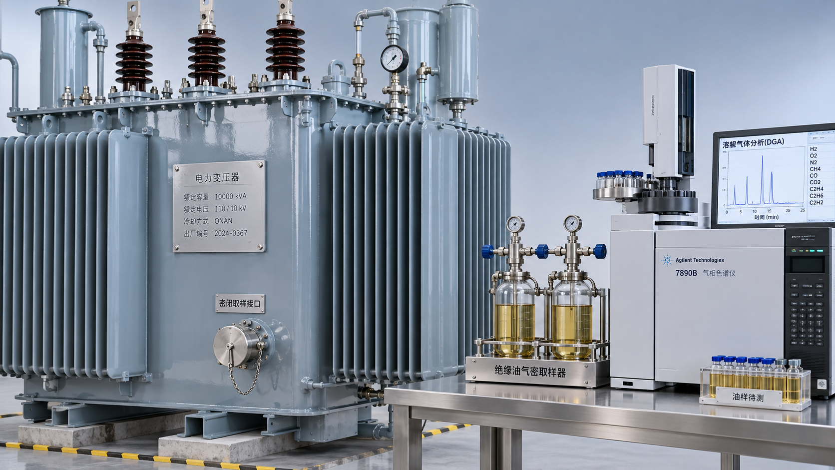
 What dissolved gas analysis reveals about an oil-immersed transformer
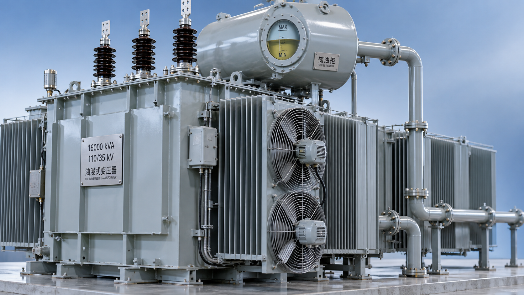
 Why an oil-cooled transformer overheats despite a normal oil level
 How the amorphous core affects SCBH15 dry-type transformer losses
 Sizing S13 oil-immersed transformers for variable wind farm output
GET A FREE QUOTE
We offer reliable products, competitive prices, and nationwide professional support, committed to providing customers with efficient and energy-saving power equipment solutions.