


How harmonic loads affect the temperature rise of an SCB11 transformer
Harmonic loads can push an SCB11 transformer beyond its expected temperature rise, even when RMS current remains within its rated limit. The issue is not simply “more current.” Nonlinear loads change the frequency content of that current, increasing winding eddy-current losses and other stray losses in ways that a conventional loading percentage does not reveal.
For installations serving variable-frequency drives, UPS systems, or rectifier-fed equipment, thermal assessment therefore needs more than nameplate kVA and current THD. It needs the harmonic spectrum, the transformer’s loss characteristics, and the actual cooling conditions. An SCB11 designation alone does not establish a harmonic loading capability.
Why rated RMS current does not guarantee rated temperature rise
An SCB11 transformer is generally a cast-resin dry-type distribution transformer. Its temperature-rise performance is established under specified test conditions. Those conditions should not automatically be treated as representative of a room full of power-electronic loads.
The basic winding resistance loss follows total RMS current squared. If two current waveforms have the same RMS value, their basic I²R losses are broadly comparable at the same winding resistance. Their additional losses, however, can differ substantially.
Harmonic currents produce higher-frequency leakage fields. These fields induce eddy currents within winding conductors and create additional heating in conductive structural parts. Skin and proximity effects also alter current distribution. Consequently, a transformer carrying distorted current can develop more heat than one carrying sinusoidal current at the same RMS amperage.
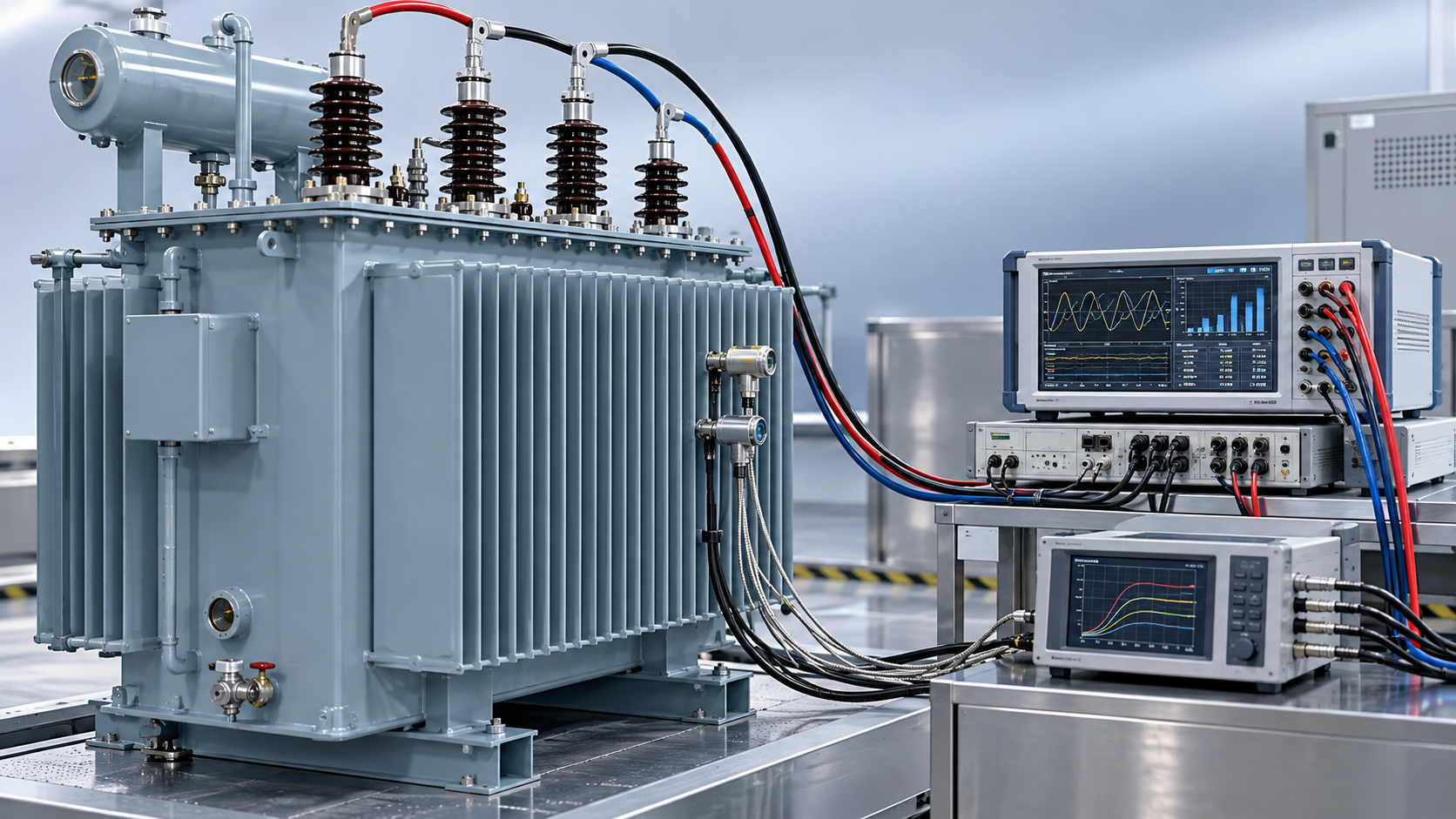
The distinction between average winding temperature and local hot-spot temperature matters here. Embedded sensors monitor particular locations; they do not necessarily identify the hottest conductor region. A reassuring temperature display is useful operating evidence, but it is not a complete validation of harmonic thermal capability.
Read the spectrum, not just the THD figure
Current THD compares the RMS sum of harmonic currents with the fundamental current. It describes distortion, but does not show where that distortion sits in the frequency spectrum. Two loads with the same THD can impose different winding eddy-current losses.
A commonly used screening relationship weights each harmonic contribution by the square of its harmonic order:
Winding eddy-current loss weighting ∝ Σ h²Ih²
Here, h is the harmonic order and Ih is the RMS current at that order. Under this simplified relationship, equal current components at the eleventh and fifth harmonics have an eddy-loss weighting ratio of 121/25. This is a mathematical illustration, not a prediction of total transformer loss: conductor geometry and frequency-dependent effects influence the actual result.
Other stray losses do not necessarily follow the same h² relationship. Applying that weighting to the entire measured load loss would overstate or misrepresent the heating. A defensible calculation separates winding resistance loss, winding eddy-current loss, and other stray loss using manufacturer-supported data.
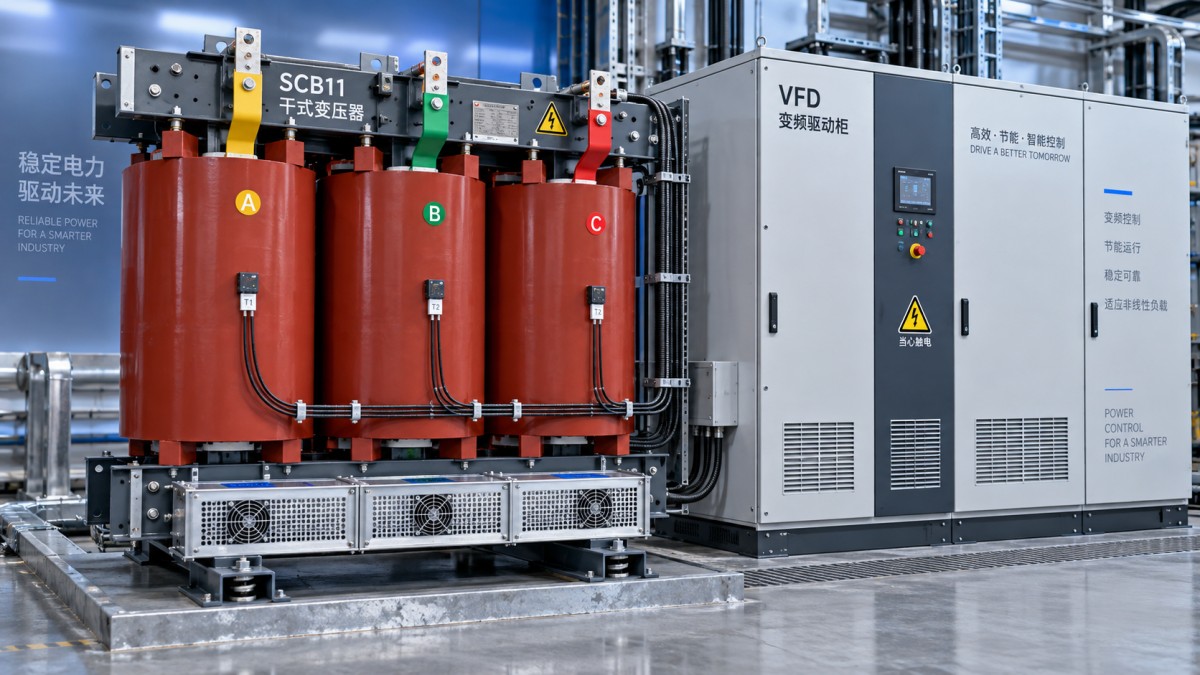
There is another practical trap: THD can rise when the fundamental current falls. A lightly loaded UPS may show high percentage distortion while producing less absolute harmonic current than at heavier load. Record harmonic amperes, RMS current, and operating state together rather than ranking thermal risk by THD alone.
The installation can make the heating problem worse
A drive-fed production line illustrates the assessment challenge. The transformer may operate comfortably during partial production, then experience sustained additional losses when several drives run together. The relevant spectrum is the aggregate current at the transformer terminals, not a simple sum of equipment datasheet THD values. Harmonic phase relationships and operating diversity affect that aggregate.
For balanced three-phase six-pulse rectifier loads, fifth and seventh harmonics commonly deserve attention. In four-wire systems supplying single-phase nonlinear equipment, triplen harmonics require a separate check of neutral loading and winding connections. A delta winding can provide a circulating path for certain zero-sequence components; it does not make their thermal consequences disappear.
Cooling conditions can turn a manageable loss increase into an operating constraint. Check enclosure restrictions, blocked air passages, room inlet temperature, ventilation capacity, and hot-air recirculation. Forced-air cooling only supports the rating stated for that cooling arrangement. Adding fans is not a substitute for confirming harmonic capability.
Derating needs a loss calculation, not a blanket percentage
There is no universal harmonic derating percentage for every SCB11 transformer. Units with the same rated power can have different conductor arrangements, eddy-loss proportions, and thermal margins. A THD-based rule may help flag a concern, but it should not become the final loading limit.
A useful technical review should establish:
- The harmonic spectrum on each phase across representative operating conditions, including sustained high-load periods.
- The manufacturer’s reference load losses, their temperature basis, and the loss separation used for harmonic assessment.
- The applicable cooling rating, ambient conditions, altitude, and enclosure arrangement.
- The allowable continuous load, temperature-rise limits, and protection settings for the proposed duty.
IEEE C57.110 provides guidance for assessing transformer capability with nonsinusoidal load currents. IEC 60076-11 addresses dry-type transformer requirements. Their applicable editions and contractual relevance should be confirmed for the project. A harmonic loss factor or K-factor can support the discussion, but neither should be interpreted as a stand-alone temperature-rise guarantee.
Voltage distortion also deserves measurement. Current harmonics primarily drive additional load losses, while distorted supply voltage can affect core losses. Keeping these mechanisms separate prevents an investigation from attributing every temperature increase to winding current alone.
What to ask the supplier—and what an alternative design changes
Jiangsu Shengda Power Equipment Co., Ltd. supplies SCB-series dry-type transformers alongside oil-immersed units and compact substations. For a harmonic-duty enquiry, the useful request is a documented thermal assessment against the proposed spectrum—not simply confirmation that an SCB11 model is available.
The company’s published information lists ISO9001 certification and references GB1094.1-2-1996 and GB/T6451-2008. Quality-system certification does not establish a particular unit’s harmonic loading capacity. Those dated standard references should also be checked against the current project specification and applicable dry-type requirements.
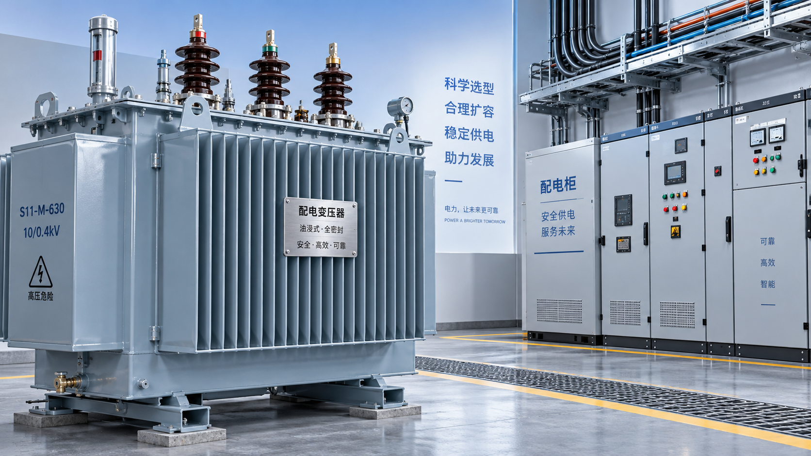
Where fire-safety rules, location, and maintenance arrangements permit, the S11 Series Oil-Immersed Power Transformer may be considered as a separate design option. Its listed silicon-steel core, oxygen-free copper windings, and fully sealed corrugated-tank construction address materials and oil-system design. They do not, by themselves, establish harmonic mitigation. Oil cooling changes heat removal; harmonic losses still require evaluation.
For an existing installation, capture synchronized current spectra, loading, ambient temperature, and winding temperature trends before changing capacity or cooling. For a new installation, submit the expected nonlinear-load profile with the enquiry. The acceptance criterion should be explicit: the transformer must meet its agreed thermal limits under the specified harmonic duty, not merely carry the required RMS current.



 How harmonic loads affect the temperature rise of an SCB11 transformer
 What an F1 fire behaviour rating means for a flame-retardant transformer
 How enclosure specifications affect SCB18 dry-type transformer cost
 How to compare loss guarantees for S22 oil-immersed transformers
 When to choose a loop-feed pad-mounted transformer over radial feed
 How much spare capacity should a distribution transformer have?
GET A FREE QUOTE
We offer reliable products, competitive prices, and nationwide professional support, committed to providing customers with efficient and energy-saving power equipment solutions.