


How much spare capacity should a distribution transformer have to accommodate load growth without adding unnecessary capital cost and no-load losses? A 15–25% allowance above calculated peak demand can be a useful starting point for planning, but it is not a universal design rule. The right rating depends on load diversity, power factor, harmonics, ambient conditions, expansion plans, and the consequences of an outage.
For technical evaluators, the real question is not simply how much unused capacity to buy. It is how much usable capacity will remain under the conditions the transformer actually experiences—and whether that reserve is worth its lifetime cost.
Define “spare capacity” before comparing ratings
Two commonly used percentages describe different things. A margin above demand is calculated against the load; unused capacity is calculated against the transformer rating.
- Sizing margin: (transformer rating − demand) ÷ demand.
- Unused capacity: (transformer rating − demand) ÷ transformer rating.
A 1,000 kVA transformer supplying 800 kVA has a 25% sizing margin above demand, but only 20% of its rated capacity is unused. Confusing these definitions can make otherwise reasonable proposals look inconsistent.
State the basis explicitly in the specification. For example: “Provide at least 20% capacity above the forecast coincident peak demand, after accounting for site-related capacity reductions.” That wording is more useful than “allow 20% spare.”
Establish the load the transformer will actually see
Start with coincident peak demand, not the sum of equipment nameplates. In a factory, compressors, process heaters, ventilation, and production machinery rarely reach maximum demand together. However, assumed diversity must reflect operating schedules rather than an optimistic estimate.
For an existing installation, review interval-meter data over representative production cycles and seasons. Check whether shutdowns, unusually low output, or missing seasonal loads have understated the recorded peak. For a new installation, build a load schedule showing operating demand, power factor, duty cycle, and credible simultaneous operation.
Where harmonic distortion is limited, apparent power can be estimated as:
Demand in kVA = demand in kW ÷ power factor
A 450 kW coincident load at 0.90 power factor therefore represents approximately 500 kVA. For nonlinear loads, use true power factor or measured apparent power rather than displacement power factor alone.
Motor starting deserves a separate check. A transformer may have sufficient continuous capacity yet produce unacceptable voltage dips during a large motor start. Transformer impedance, upstream network strength, starting method, and other connected loads all influence the result. A generic spare-capacity percentage cannot replace that assessment.
Turn a planning allowance into a defensible rating
A practical sizing sequence separates known growth from operating reserve:
- Calculate the present coincident peak in kVA.
- Add justified expansion demand over the chosen planning horizon.
- Apply an operating allowance suited to uncertainty and service requirements.
- Verify usable capacity under site conditions.
- Select a standard rating and check voltage performance, protection, and losses.
Keeping these steps separate prevents double counting. If a forecast already contains a generous allowance for uncertain expansion, adding another large “future growth” percentage may inflate the rating without improving the decision.
A worked selection example
Consider an installation with 450 kW peak demand at 0.90 power factor. Planned expansion is expected to increase coincident apparent-power demand by 15%. The evaluator then applies a separate 20% operating allowance.
The 800 kVA candidate would operate at about 72% of rating at the forecast peak, before any site-related capacity adjustment. The resulting reserve exceeds the original 20% allowance because ratings are discrete, not continuously selectable.
Now suppose the manufacturer’s assessment establishes that this installation permits only 85% of nameplate capacity. The 800 kVA unit would provide 680 kVA of usable capacity—below the 690 kVA planning requirement. A higher rating, improved ventilation, or another engineering change would then require evaluation. The 85% figure is illustrative, not a standard derating factor.
When the initial 15–25% allowance needs revision
Heat, altitude, and enclosure conditions
High ambient temperature, restricted airflow, altitude, and nearby heat sources can reduce thermal capability. The temperature around the installed transformer matters more than a regional weather average. Compact substations and indoor rooms warrant particular attention to ventilation and heat removal.
Confirm the specified service conditions and obtain the manufacturer’s thermal assessment where conditions differ from the rating basis. IEC 60076-7 provides loading guidance for mineral-oil-immersed transformers, while IEC 60076-12 addresses dry-type transformers. Apply the relevant contractual standards and current project requirements rather than assuming every published rating is interchangeable.
Harmonics and uneven phase loading
Variable-speed drives, UPS equipment, rectifiers, and other nonlinear loads can increase winding eddy-current and stray losses. Two installations drawing the same kVA may therefore impose different thermal stress.
Provide the manufacturer with the expected harmonic spectrum or representative measurements. A larger conventional unit is not automatically equivalent to a transformer evaluated for harmonic-rich service. Also check phase currents: an acceptable aggregate three-phase demand can conceal an overloaded phase.
Expansion uncertainty and critical service
Documented expansion is easier to justify than an undefined expectation that “the site will grow.” Identify the equipment, its likely installation date, and its contribution to simultaneous demand. Where growth remains uncertain, compare staged expansion with buying all anticipated capacity immediately.
Critical facilities may need more than spare kVA. Redundant transformers, sectionalized busbars, automatic transfer arrangements, or load shedding can address failure scenarios that one oversized transformer cannot. Capacity reserve and supply redundancy are different design decisions.
Compare lifetime losses, not just percentage loading
Oversizing does not automatically improve efficiency. No-load losses continue whenever the transformer is energized, even when demand is low. Load losses generally increase approximately with the square of load current, subject to temperature and harmonic effects.
For a preliminary comparison using manufacturer data:
Annual loss energy ≈ P0 × energized hours + Σ[Pk × load fraction² × interval hours]
Here, P0 is no-load loss and Pk is rated load loss, expressed in kW. Use a representative load profile; a single annual average can obscure short peaks and long lightly loaded periods. Include purchase cost, installation constraints, energy prices, and anticipated utilization in the comparison.
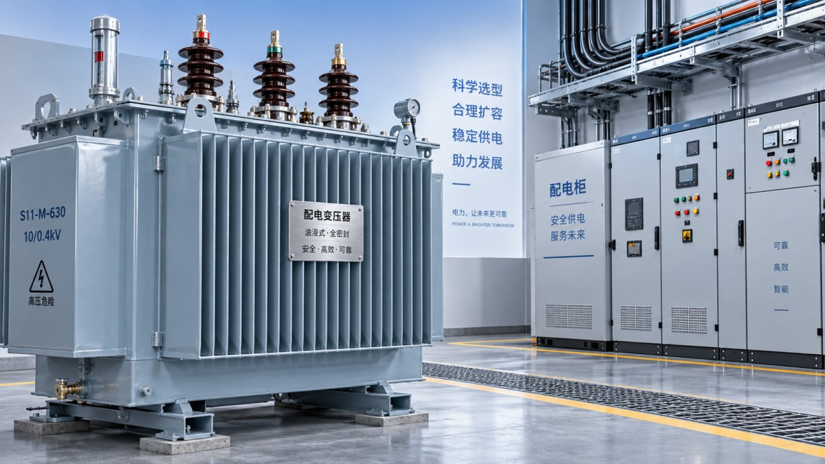
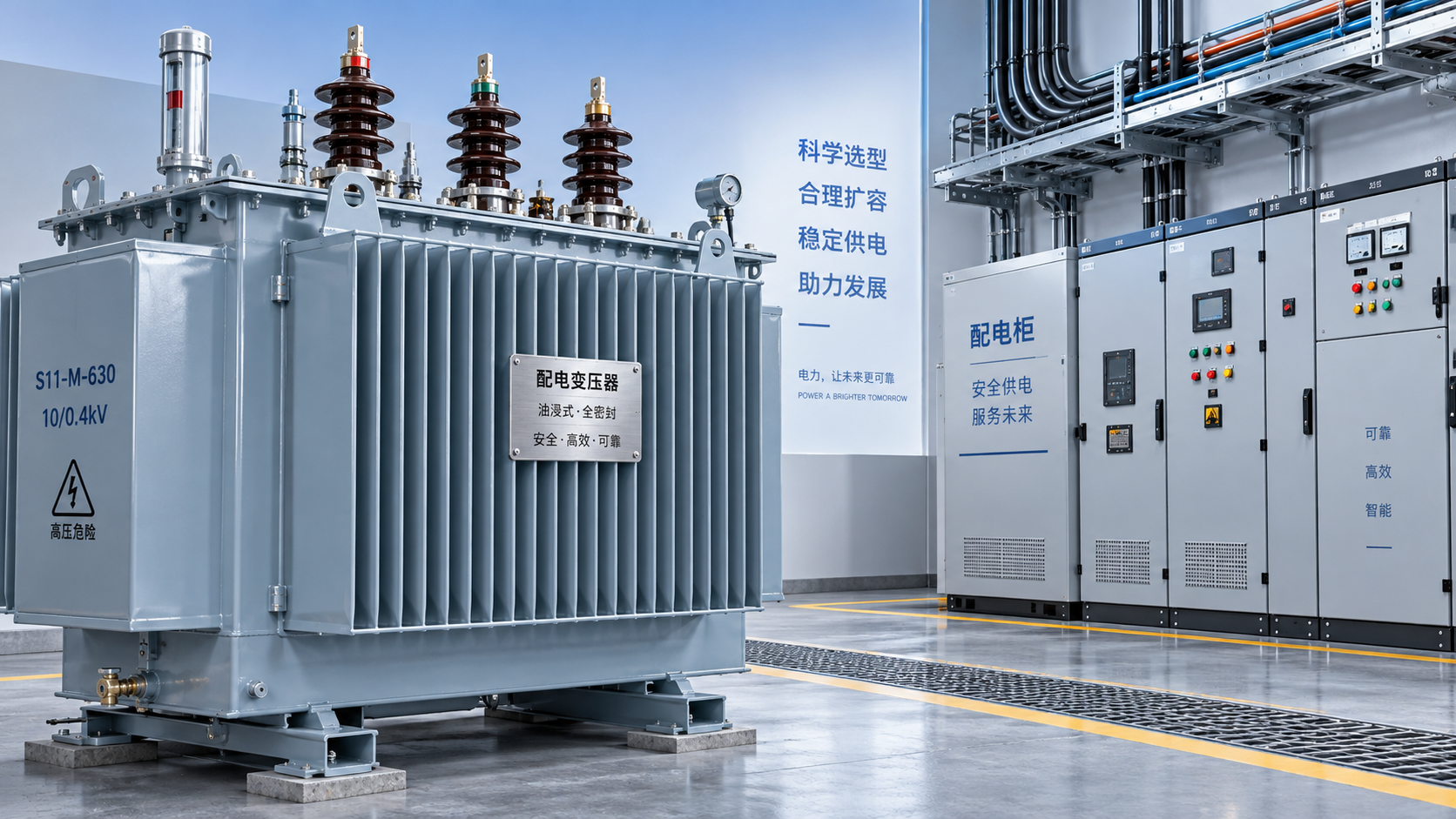
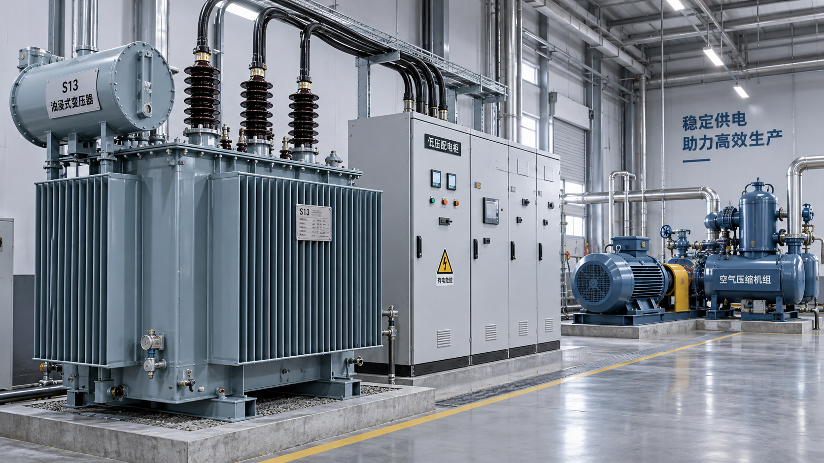
For an oil-immersed installation, Jiangsu Shengda Power Equipment Co., Ltd.’s S11 Series Oil-Immersed Power Transformer offers ratings from 30 to 2,500 kVA. Its specified silicon-steel core, oxygen-free copper windings, and fully sealed corrugated-tank construction are relevant to loss and maintenance evaluations. The sealed design limits contact between insulating oil and air; it does not remove the need for routine external inspection and condition checks.
When comparing candidate ratings, request model-specific no-load loss, load loss, impedance, temperature-rise data, and applicable test documentation. Do not infer harmonic capability or a particular efficiency level from the series designation alone.
The selection should explain why the reserve exists
A defensible distribution transformer selection records the present demand, forecast growth, reserve definition, site limitations, and chosen standard rating. It also confirms motor-starting performance, fault levels, protection coordination, and the economic effect of losses.
Use 15–25% above calculated peak demand as an initial assumption—not a guaranteed answer. Where conditions are well understood and growth is limited, less reserve may be justified. Where thermal constraints, uncertain expansion, or difficult replacement make undersizing costly, more may be appropriate. The best choice is the rating whose usable capacity and lifecycle cost fit the installation, with every allowance traceable to a real requirement.



 How much spare capacity should a distribution transformer have?
 Checking S13 oil-immersed transformers for renewable inverter loads
 How to assess environmental claims for SCB13 dry-type transformers
 Sizing an S13 oil-immersed transformer for industrial motor starting
 What enclosure protection does an SCB13 transformer need against dust?
 How to verify the temperature-rise test of an SCB12 dry-type transformer
GET A FREE QUOTE
We offer reliable products, competitive prices, and nationwide professional support, committed to providing customers with efficient and energy-saving power equipment solutions.