


A solar or wind project can stay within its transformer’s rated power and still encounter excessive heating, voltage trips, or protection problems. Inverter current waveforms, reactive power requirements, and grid-side voltage conditions can impose demands that a conventional nameplate does not describe. These gaps can lead to procurement changes or commissioning delays.
An S13 Series Oil-Immersed Power Transformer for renewable energy should therefore be accepted against the project’s actual electrical duty, not the S13 designation alone. The core checks are voltage and winding compatibility, harmonic-related losses, thermal capability, and protection coordination. Obtain written confirmation for the proposed configuration before treating a standard distribution transformer as suitable for inverter service.
Define the duty before comparing transformer quotations
Start with the inverter output specifications and the grid connection requirements. Solar and wind systems do not necessarily present the same transformer duty: converter topology, collection voltage, earthing arrangement, and operating profile all affect the selection. A quotation based only on installed generation capacity leaves important assumptions unresolved.
Provide suppliers with a duty schedule that identifies:
- Maximum continuous active power and simultaneous reactive power requirements at the transformer terminals.
- Inverter output voltage range, operating frequency, and permitted voltage imbalance.
- Current harmonic spectrum at relevant operating points, including reduced output and reactive-power operation.
- Expected loading duration, generation ramps, nighttime operation, and any reverse-power duty.
- Ambient temperature, altitude, installation conditions, and cooling restrictions.
- Grid fault level, earthing arrangement, and required fault ride-through behavior.
Size for apparent power, not active power alone. Where active power and reactive power are delivered simultaneously, the fundamental-frequency apparent power follows S = √(P² + Q²). Harmonic current adds heating that this calculation does not capture. Evaluate the maximum permitted operating combinations rather than combining unrelated maxima that cannot occur together.
Resolve voltage, vector group, and earthing compatibility
Confirm that the transformer’s low-voltage winding matches the inverter terminal voltage and that its high-voltage winding matches the collection system. Check the full operating voltage range, including cable voltage rise during export, rather than matching nominal voltages only. An unsuitable ratio can push an inverter toward its voltage limit before full generation is reached.
Tap selection needs the same attention. Establish the required adjustment range and whether taps are changed only while de-energized or through an on-load arrangement. Do not assume that a standard off-circuit tap changer can regulate changing grid conditions during operation.
The vector group and neutral arrangement must agree with both the inverter manufacturer’s requirements and the plant earthing design. Winding connections influence phase displacement and zero-sequence current paths. They may also affect how certain harmonic components circulate or propagate, but a delta winding does not eliminate all harmonic exposure.
Ask the inverter supplier about permitted grounding configurations, common-mode voltage behavior, and any transformer insulation requirements associated with switching. These cannot be inferred from the S13 series name.
Use harmonic data to assess losses and temperature rise
A low-loss designation is not proof of suitability for a distorted current waveform. Harmonics can increase winding eddy-current and stray losses; equal RMS currents with different harmonic spectra may produce different heating. A single current THD value is useful for screening, but insufficient for a dependable thermal assessment.
Request harmonic magnitudes by order, with the measurement or calculation point clearly identified. Inverter-terminal data and transformer-terminal data may differ because of filters, cables, and network interactions. Where switching-frequency components are relevant, ask both suppliers how those components are included in their assessment.
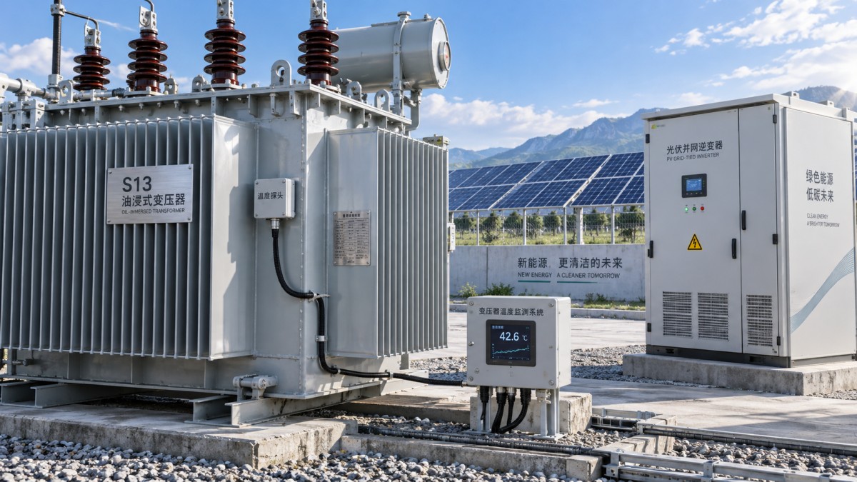
Generic harmonic withstand statements should not replace an assessment tied to the offered transformer. If derating is proposed, require its calculation basis and resulting usable capacity. Alternatives may include a larger rating or a winding design adapted to the specified duty, subject to the supplier’s engineering review.
Site conditions can invalidate an otherwise adequate calculation. Restricted ventilation, enclosure heating, altitude, and sustained high ambient temperatures must be reflected in the thermal evaluation. A short generation peak and a prolonged high-load period should not be treated as equivalent.
Check impedance and protection as one system
Transformer impedance affects voltage regulation and fault current. Lower impedance may reduce voltage change under load but increase fault duty; higher impedance may constrain voltage performance during active and reactive power operation. Use the offered impedance, including its tolerance, in the plant load-flow and short-circuit studies.
Protection coordination requires more than matching fuse or breaker ratings to transformer current. Inverters often limit fault current, so protection selected around conventional rotating-machine assumptions may not detect every fault as intended. The study should distinguish grid-fed faults, inverter-fed faults, transformer energization inrush, and permitted operating transients.
Confirm the duties and settings of high-voltage protection, low-voltage protection, earth-fault protection, and any transformer differential scheme. Temperature, pressure, and oil-related protective devices should be specified according to the actual transformer construction. Agree which signals initiate alarms, inverter shutdown, or breaker trips, and verify the interfaces before delivery.
When a compact substation is part of the layout
Space and installation interfaces may favor an integrated package rather than separately installed equipment. The ZGS Combined Substation combines the transformer body, switchgear, fuses, tap changers, low-voltage distribution equipment, and auxiliary equipment. Its supplied parameter range is 63–1600 kVA, 50 Hz, and 6–10 kV; configurations can include metering, reactive power compensation, and low-voltage branching.
This option is relevant only where those parameters fit the project. Its compact structure and indoor or outdoor installation options can simplify layout planning, but do not establish renewable-inverter compatibility. Apply the same harmonic, thermal, earthing, and protection checks to the integrated package, including enclosure effects. Do not use a general load-capacity claim as permission to exceed the agreed continuous rating.
Turn supplier evidence into procurement and commissioning gates
Before purchase approval, obtain a datasheet for the exact offered unit, an approved connection diagram, guaranteed losses and impedance, the thermal assessment, and a list of applicable standards with editions. Confirm which test reports apply to the offered design and which tests will be performed on the supplied unit. A catalogue statement cannot resolve configuration-specific questions.
- Before manufacture: close unresolved assumptions about inverter duty, winding connections, taps, insulation, cooling, and protective interfaces.
- Before shipment: review agreed factory test results and confirm that the supplied configuration matches the approved documents.
- Before energization: have qualified personnel verify earthing, phase relationships, tap position, oil condition where applicable, protection settings, and interlocks under the approved commissioning procedure.
- During staged loading: record terminal voltages, current distortion, temperature trends, and protection events at defined operating points.
Initial energization does not demonstrate full-load thermal suitability. Establish acceptance limits in advance and compare temperatures only after allowing for thermal response and ambient conditions. Unexpected temperature rise, abnormal noise, repeated voltage trips, or unexplained protection operation should trigger investigation before higher loading. Approval should rest on documented compatibility and measured behavior, not simply on the absence of an immediate trip.



 Checking S13 oil-immersed transformers for renewable inverter loads
 How to assess environmental claims for SCB13 dry-type transformers
 Sizing an S13 oil-immersed transformer for industrial motor starting
 What enclosure protection does an SCB13 transformer need against dust?
 How to verify the temperature-rise test of an SCB12 dry-type transformer
 Distribution transformer maintenance tips for spotting oil leaks
GET A FREE QUOTE
We offer reliable products, competitive prices, and nationwide professional support, committed to providing customers with efficient and energy-saving power equipment solutions.