


Size an S13 oil-immersed transformer against two separate limits: the plant’s continuous apparent-power demand and the voltage drop during the most demanding credible motor start. A transformer that carries the running load comfortably can still allow a large compressor or pump to pull the low-voltage bus down far enough to interrupt controls, trip drives, or prevent another motor from accelerating.
For an S13 Series Oil-Immersed Power Transformer for industrial use, begin with the operating load schedule, then check starting current, transformer impedance, upstream supply strength, and feeder impedance. Select the rating only after both running capacity and starting performance pass. Where starting voltage is the limiting factor, changing the starting method or sequence may be more economical than increasing transformer capacity.
Build the load schedule around actual operating combinations
Adding motor nameplate kilowatts does not establish transformer kVA. Motor ratings normally describe mechanical shaft output; transformer loading depends on electrical input, efficiency, and power factor. Include lighting, process heaters, drives, control supplies, and other loads sharing the same transformer.
For a three-phase motor at its intended operating point:
Electrical input kW = shaft output kW ÷ efficiency
Motor kVA = electrical input kW ÷ power factor
Line current = motor kVA × 1,000 ÷ (√3 × line voltage)
Use manufacturer data at the expected load point rather than assuming every motor operates at full load. For the overall plant, sum real power and reactive power for each operating combination, then calculate total apparent power. Arithmetic addition of individual kVA values can provide a conservative preliminary estimate, but it does not capture differing power factors precisely.
- Separate continuously operating equipment from standby equipment that cannot run simultaneously.
- Identify the maximum production combination, not just the average shift demand.
- Record planned additions separately so expansion allowance remains visible.
- Include harmonic-producing loads and request any necessary transformer thermal assessment.
The initial rating must carry this demand under the specified cooling and installation conditions. Do not apply an unexplained spare-capacity percentage as a substitute for identifying future loads.
Define the start that the transformer actually has to support
The largest motor is not automatically the worst starting event. A smaller motor starting against high mechanical load, through a long feeder, while the rest of the plant is operating may create the more difficult condition.
For each significant motor, obtain rated current, locked-rotor current or starting-current curves, starting power factor where available, acceleration time, and permissible starts per hour. Record driven-load torque and inertia. A loaded compressor, for example, presents a different acceleration requirement from an unloaded machine even when the motor ratings match.
Distinguish motor current from supply current, especially with a variable-frequency drive. The transformer supplies the drive input, not the motor’s direct-on-line locked-rotor current.
Also define restart behavior after a supply interruption. Several motors restarting together can be more severe than the normal production sequence. Any assumed sequencing should be implemented in the controls, rather than left as an operating instruction.
Screen voltage dip, then model the complete supply path
Transformer percentage impedance is central to the starting check. For a preliminary transformer-only screen:
Approximate voltage-drop magnitude (%) ≈ starting current ÷ transformer rated secondary current × transformer impedance (%)
This estimates the magnitude of the transformer’s impedance voltage drop under simplified assumptions. It is not a guaranteed bus-voltage dip: actual voltage depends on resistance, reactance, starting power factor, existing load, and the change in motor current as voltage falls. Use the result to identify candidates requiring closer analysis, not as final acceptance evidence.
The full calculation should include the utility or upstream source impedance, transformer impedance, bus connections, and motor feeder. Assess voltage at both the common bus and the motor terminals. A healthy bus voltage does not rule out excessive drop along a long cable.
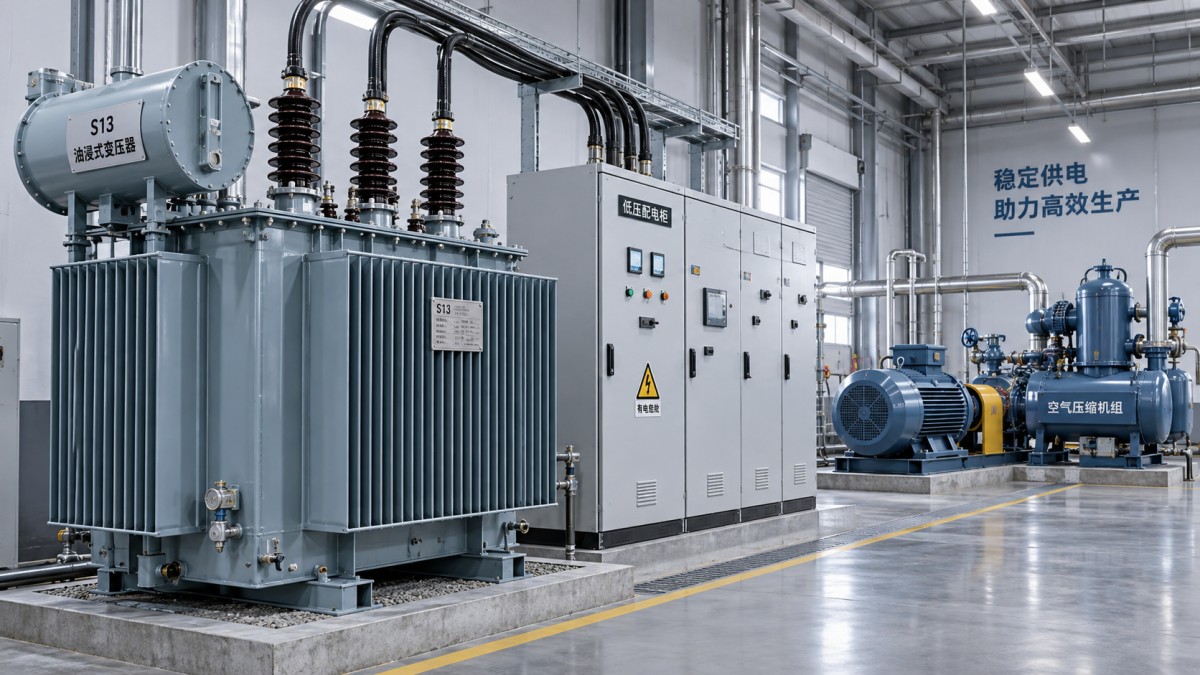
Set allowable voltage depression from equipment requirements. Contactors, control power supplies, drives, and process instrumentation may have different voltage-and-duration tolerances. There is no single acceptable dip percentage for every industrial installation.
For induction motors, starting torque approximately follows the square of applied voltage under comparable conditions. Reduced voltage can therefore extend acceleration or prevent it entirely. Where the preliminary result is marginal, use a dynamic motor-starting study to check voltage recovery, acceleration time, and the response of other running motors.
Choose between more capacity and a less demanding start
If continuous loading passes but motor starting fails, compare corrective options before purchasing a larger transformer.
- Separate starts. Delay nonessential motors until the first motor reaches operating speed. Check that the sequence also applies after outages and emergency shutdowns.
- Reduce mechanical starting load. Confirm whether the process permits compressor unloading or another manufacturer-approved starting arrangement.
- Change the starter. A soft starter or drive may reduce supply demand, but its settings and torque capability must suit the driven equipment.
- Address feeder drop. Review cable length, conductor size, and connections where motor-terminal voltage is the limiting factor.
- Reassess transformer rating and impedance. Compare candidate units using their actual offered parameters, not the S13 designation alone.
A larger transformer generally reduces its contribution to starting voltage drop when percentage impedance is comparable. It also changes prospective fault current and may require different switchgear or protection settings. Lower impedance has the same trade-off: better voltage stiffness can mean greater short-circuit duty. Neither choice removes a weak upstream supply.
Check installation constraints before freezing the transformer type
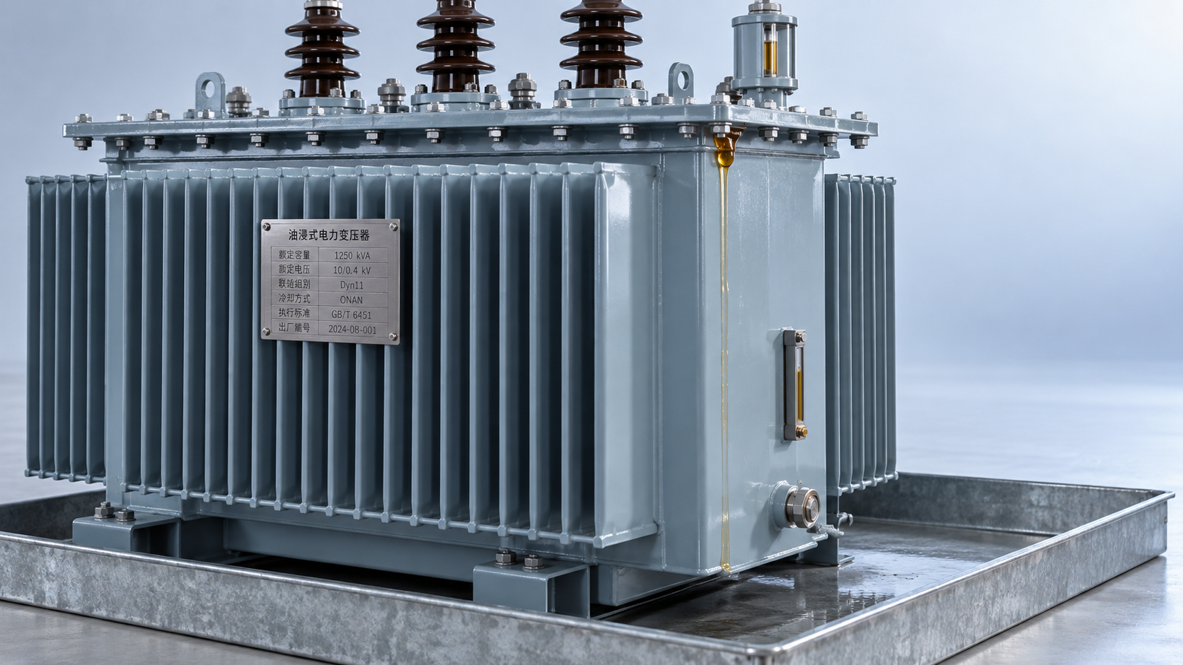
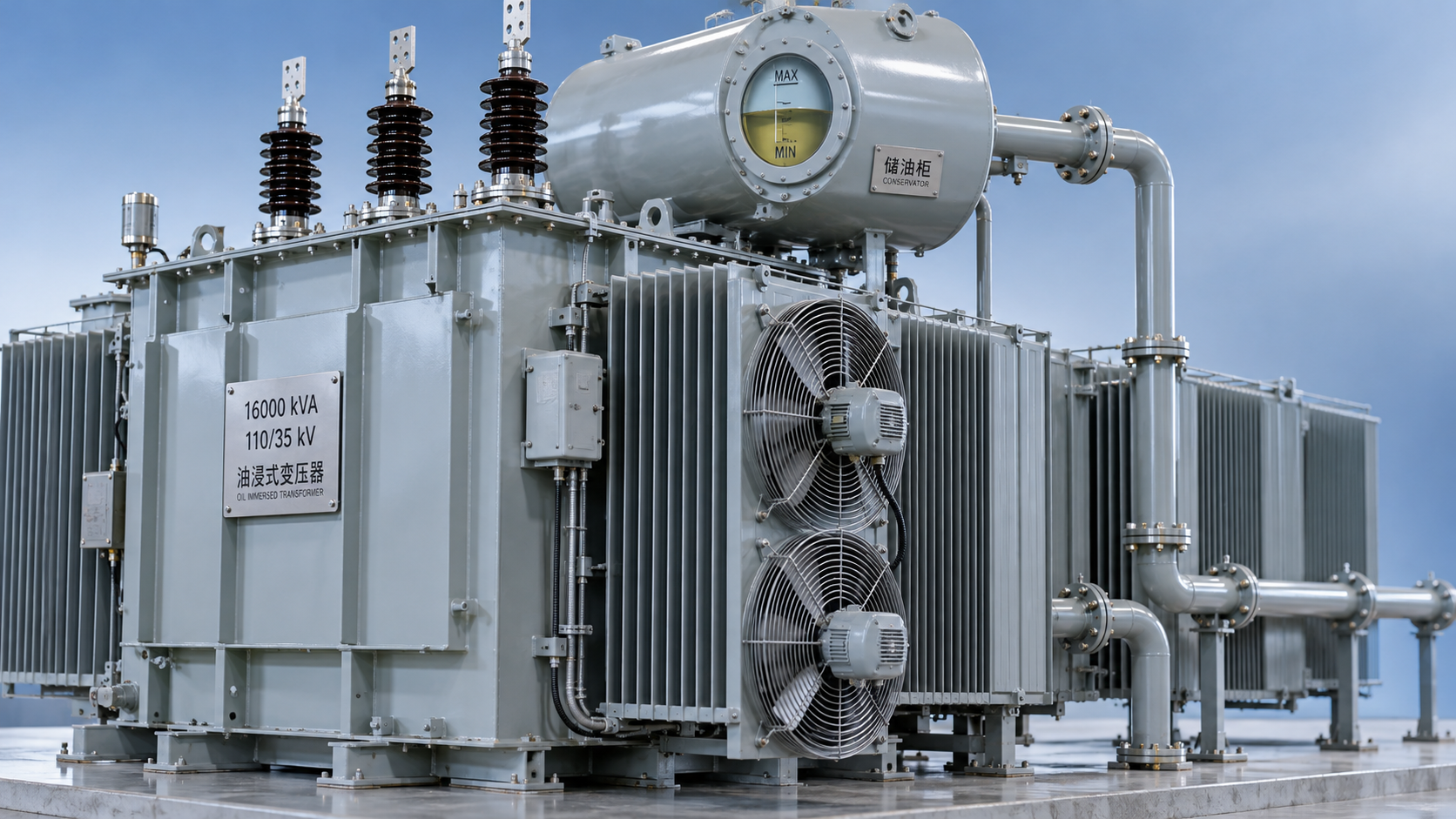
An oil-immersed selection also requires review of ambient temperature, altitude, ventilation, oil containment, access, and applicable fire provisions. The available rating must match the specified service conditions; a nominal kVA value does not override cooling limitations.
Where the installation brief calls for dry-type equipment instead, the SCBH15 Type Dry-Type Transformer is an alternative to evaluate, not an S13 oil-immersed variant. Its supplied product information identifies amorphous-alloy construction, low no-load loss, and a temperature-control and protection system. Those features may inform an installation comparison, but do not establish motor-starting suitability. Obtain its rating, impedance, cooling duty, and load data before applying the same starting checks.
Put measurable acceptance conditions into the purchase specification
Request guaranteed transformer rating, voltage ratio, tap range, percentage impedance and tolerance, losses, vector group, and applicable service conditions. Supply the motor-starting schedule and upstream fault-level information so the proposed transformer can be checked against the actual network.
The specification should state the minimum acceptable voltage at critical buses and motor terminals, the maximum acceptable acceleration time, and the required starting frequency. Verify protection coordination against motor-starting current, transformer energization inrush, and fault duty as separate events. Raising protection thresholds merely to avoid trips can compromise fault protection.
During commissioning, record bus voltage, motor-terminal voltage, current, and acceleration time for the agreed worst operating combination. Investigate deviations through starter settings, supply conditions, feeder drop, and mechanical load before changing protection. Acceptance should demonstrate that the selected rating supports the defined operating sequence—not simply that the motor starts once with the rest of the plant switched off.



 Sizing an S13 oil-immersed transformer for industrial motor starting
 What enclosure protection does an SCB13 transformer need against dust?
 How to verify the temperature-rise test of an SCB12 dry-type transformer
 Distribution transformer maintenance tips for spotting oil leaks
 What dissolved gas analysis reveals about an oil-immersed transformer
 Why an oil-cooled transformer overheats despite a normal oil level
GET A FREE QUOTE
We offer reliable products, competitive prices, and nationwide professional support, committed to providing customers with efficient and energy-saving power equipment solutions.