


An SCB11 dry-type transformer room needs enough ventilation to remove the transformer’s operating losses while keeping the air entering its cooling passages within the manufacturer’s permitted temperature range. As a preliminary estimate, each 1 kW of heat requires approximately 300 m³/h of airflow for a 10°C increase between supply and exhaust air. A room releasing 10 kW of heat would therefore need roughly 3,000 m³/h under those assumptions.
That figure is a heat-balance estimate, not a universal ventilation requirement. Actual airflow depends on transformer losses, loading, incoming air temperature, other equipment in the room, and resistance through louvers, filters, and ducts. For an SCB11 Type Dry-Type Transformer installation, room volume alone cannot establish whether cooling will be adequate.
Calculate the heat load before sizing the ventilation
Start with the transformer’s no-load loss and load loss at the specified reference temperature. Its kVA rating describes electrical capacity; it does not tell the ventilation designer how much heat the room must remove. Two transformers with the same rating can impose different cooling demands.
For preliminary planning, transformer heat loss can be estimated as:
Transformer heat loss ≈ no-load loss + rated load loss × load fraction²
No-load loss remains present while the transformer is energized. Load loss changes approximately with the square of current. This approximation is useful for an initial room calculation, but the final design should use manufacturer loss data and account for operating temperature, harmonics, and any intended overload duty.
Consider an illustrative transformer with 2 kW of no-load loss and 8 kW of rated load loss. At 80% load, estimated transformer losses are 2 + 8 × 0.8² = 7.12 kW. If other equipment releases another 1 kW into the room, the ventilation calculation starts from approximately 8.12 kW. These values illustrate the method; they are not specifications for a particular SCB11 model.
Use the highest credible sustained operating condition. An average daily load can conceal a demanding afternoon peak, especially when that peak coincides with hot outdoor air. Where two transformers share a room, calculate their combined losses for the operating arrangements the project actually permits.
Transformer selection can also change the ventilation requirement. An amorphous-core option such as the SCBH15 Type Dry-Type Transformer may reduce the continuous heat contribution from no-load losses. Compare guaranteed no-load and load losses at the required rating and duty before changing the room design; lower core loss alone does not determine total heat at high loading.
Convert heat loss into airflow—and check the temperature assumption
The sensible-heat relationship provides a practical starting point:
Airflow Q = 3,600 × P ÷ (ρ × cp × ΔT)
Here, Q is airflow in m³/h, P is the heat to be removed in kW, ρ is air density in kg/m³, cp is air’s specific heat in kJ/(kg·°C), and ΔT is the increase from incoming air to exhaust air. Using approximate near-sea-level values of 1.2 kg/m³ and 1.0 kJ/(kg·°C), the relationship becomes:
Q ≈ 3,000 × P ÷ ΔT
For the illustrative 8.12 kW room heat load, a 10°C air temperature increase gives approximately 2,440 m³/h. Reducing the permitted increase to 5°C doubles the estimated airflow to about 4,880 m³/h. These are required air volumes through the effective cooling route, before selecting a fan against system resistance.
The temperature assumption deserves as much attention as the calculation. Winding temperature rise is not the allowable room-air temperature increase. Winding limits, cooling-air limits, and exhaust temperature describe different conditions. The temperature at the transformer’s cooling-air intake must remain acceptable even if the room’s average temperature appears reasonable.
If incoming outdoor air is already near the manufacturer’s maximum permitted cooling-air temperature, increasing ventilation offers limited relief. Ventilation can remove heat, but cannot cool incoming air below its source temperature. A cooler intake location, conditioned supply air, or a revised operating arrangement may then be necessary. At altitude, use the appropriate air density and address transformer derating separately.
When will natural ventilation be enough?
Natural ventilation can work where the room has a clear low-level inlet, a high-level outlet, sufficient vertical separation, and openings large enough to pass the required air. It becomes harder to justify where air must travel through long ducts, restrictive louvers, filters, or complex fire-rated routes.
An airflow requirement does not directly specify a natural ventilation opening size. Available airflow depends on buoyancy pressure, opening resistance, vertical separation, and the temperature difference that develops. A mechanical engineer should check these conditions rather than applying a fixed opening area per transformer kVA.
Distinguish the opening’s overall dimensions from its net free area. Louvers, screens, and protective grilles reduce the area available for airflow. A large wall opening can still restrict cooling once its complete assembly is installed.
Mechanical ventilation is easier to control when the heat load is substantial, outdoor conditions vary widely, or the room geometry provides little buoyancy pressure. Fan selection must use the required airflow at the calculated system pressure. A fan’s free-air rating can overstate what it delivers through the installed ventilation route.
Filters, louvers, duct bends, silencers, and fire dampers all contribute resistance. If filtration is necessary, allow for its loaded condition and maintenance access. For installations where loss of ventilation would interrupt critical service, decide how fan failure will be detected and whether standby capacity is warranted.
Make the airflow pass through the transformer
Position incoming air so it reaches the lower cooling passages, then provide an escape route for heated air at high level. Keep the manufacturer’s specified clearances around the enclosure and cooling openings. Cable trays, partitions, and stored materials can obstruct the intended route even when the ventilation equipment has adequate capacity.
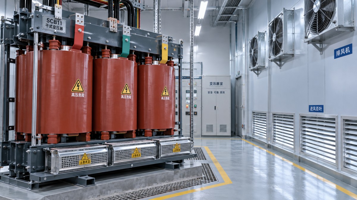
A common design weakness is airflow short-circuiting: fresh air travels directly from the inlet to a nearby extract point while warm air remains around the transformer. Room layout should encourage air to sweep the equipment rather than bypass it. With multiple transformers, avoid feeding one unit with another unit’s heated discharge.
Outdoor terminals need similar attention. Exhaust air should not be drawn back into the intake, and the intake location should address rain, dust, and site contaminants. Where fire separation affects the ventilation route, coordinate openings, ducts, dampers, and controls with the applicable building and electrical requirements.
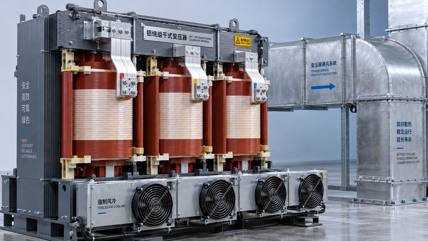
Transformer-mounted fans and room ventilation perform different jobs. Winding fans improve local heat transfer; the room system removes that heat from the space. If forced cooling enables higher loading, calculate room ventilation for the resulting losses. An air-cooled capacity statement does not establish unrestricted continuous overload capability.
Close the design with measurable acceptance criteria
Before equipment orders and room openings are finalized, align the transformer supplier’s cooling requirements with the ventilation designer’s heat-load calculation. The project should have an agreed operating load, incoming-air design temperature, airflow requirement, and response to ventilation failure.
- Obtain guaranteed losses, cooling mode, permitted ambient conditions, and enclosure clearance requirements.
- Check delivered airflow against the resistance of the complete installed ventilation route.
- Coordinate fan controls, temperature alarms, and any load-reduction or trip response.
- Provide access for cleaning cooling passages, servicing fans, and replacing filters where fitted.
At commissioning, verify airflow and record temperatures near the transformer’s cooling-air intake as well as at the exhaust. A lightly loaded commissioning test cannot demonstrate performance at peak load and peak outdoor temperature; assess those conditions through the design calculation and, where needed, follow-up operating measurements.
The ventilation requirement is ready for approval when the project can state how much heat must leave the room, how much air will actually pass through it, and what temperature will reach the transformer under the demanding operating condition. Those three figures give the project manager a defensible basis for accepting the room design.



 How much ventilation does an SCB11 dry-type transformer room need?
 How winding material affects SCB11 dry-type transformer cost
 What fire safety requirements apply to hospital dry-type transformers?
 How to compare dry-type transformer manufacturers by test evidence
 How to assess a custom transformer manufacturer's design capability
 When is an aluminum-wound transformer suitable for heavy loads?
GET A FREE QUOTE
We offer reliable products, competitive prices, and nationwide professional support, committed to providing customers with efficient and energy-saving power equipment solutions.