


An S20 transformer rating provides more than a nominal capacity figure. It gives technical evaluators a starting point for judging whether a unit can support the expected load, control energy losses, and fit the electrical characteristics of the network. Those judgments depend on reading capacity, losses, and short-circuit impedance together—not treating any one figure as a complete measure of performance.
The series designation alone is not a substitute for a verified data sheet. Voltage class, cooling, tap range, test conditions, and applicable standards all affect whether a particular transformer is suitable for the installation.
What rated capacity tells you—and what it does not
Rated capacity, expressed in kilovolt-amperes (kVA), is the apparent power a transformer is designed to deliver under its specified service and cooling conditions. For a three-phase unit, the relationship is:
Rated kVA = √3 × line voltage (kV) × line current (A)
Capacity is not the same as useful real power. A 1,000 kVA transformer supplying a load at 0.8 power factor delivers approximately 800 kW of real power at rated apparent power. Improving the load power factor can reduce current for a given real-power demand, but it does not change the transformer’s nameplate kVA rating.
Selection therefore begins with the site’s demand profile rather than the sum of every connected nameplate. Review peak demand, expected growth, starting loads, and the timing of simultaneous equipment operation. Also check ambient temperature, altitude, ventilation, and the specified cooling method. A unit that is adequate under standard conditions may require derating or a different design at the actual installation site.
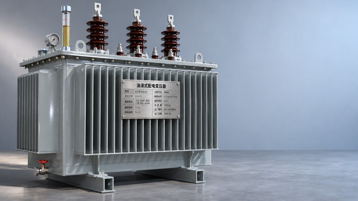
Reading S20 transformer losses correctly
Transformer losses appear mainly as no-load loss and load loss. Both become heat, but their operating patterns are different.
No-load loss: the cost of staying energized
No-load loss is measured with the transformer energized at specified voltage and frequency while the secondary is open. It is primarily associated with the magnetic core. A transformer that remains energized around the clock incurs this loss even when the connected facility is idle.
For an initial comparison, annual no-load energy can be estimated as the specified no-load loss in kW multiplied by energized hours. The result is an approximation: actual voltage and frequency, among other conditions, can affect operating loss.
Load loss: a moving target
Load loss is associated mainly with winding resistance and stray effects when current flows. It is normally stated at rated current and a specified reference temperature. For a simplified estimate at a steady load, load loss varies approximately with the square of per-unit current:
Estimated load loss ≈ rated load loss × (actual current ÷ rated current)2
At half rated current, this approximation gives one-quarter of rated load loss, not one-half. Real loads vary throughout the day, so an annual estimate should use load-profile intervals and their corresponding hours. Harmonic currents and temperature differences may make a simple square-law estimate less accurate.
For example, compare two candidates using the same expected energized hours and load profile. The unit with lower no-load loss may be attractive for a lightly loaded installation; the one with lower load loss may perform better when heavily loaded for long periods. Add the estimated energy cost to the purchase price over the chosen evaluation period, using the site’s own electricity tariff and financial assumptions.
Why impedance affects the wider system
Short-circuit impedance, usually stated as a percentage, indicates the voltage needed to circulate rated current with the other winding short-circuited, under specified test conditions. It is a key input for estimating fault current and voltage regulation.
For an illustrative transformer supplied by an ideal source, the symmetrical short-circuit current at its terminals is approximately rated current multiplied by 100 divided by the impedance percentage. Actual fault levels also depend on upstream system impedance, cables, configuration, and other sources. Use a full system study—not this approximation alone—to select switchgear and protective devices.
Higher impedance generally reduces transformer-limited fault current, but it can also increase voltage drop under load. The actual voltage change depends on both the resistance and reactance components and the load power factor. An impedance value that looks favorable for fault duty may therefore be less attractive for a site with sensitive loads or demanding motor starts.
Impedance also matters when transformers operate in parallel. Check voltage ratios, tap settings, vector groups, polarity, and compatible impedance characteristics; otherwise, circulating currents or unequal load sharing may occur. Do not assume that two units are suitable for parallel operation simply because their kVA ratings match.
Comparing specifications across series and standards
When evaluating an S20 transformer against another low-loss series, ask for guaranteed values for the exact model and tap configuration. Compare no-load and load losses at the same voltage, frequency, reference temperature, and test basis. Check whether stated values are guaranteed limits or typical figures, and identify the applicable tolerances before calculating lifecycle cost.
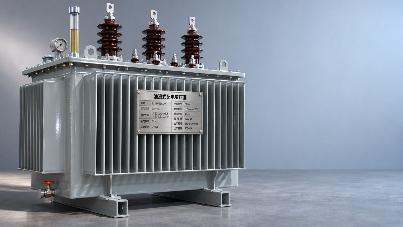
As an adjacent option for comparison, Jiangsu Shengda Power Equipment offers S22 Series Oil-Immersed Power Transformers, with listed models spanning 30 to 2,500 kVA in the 10 kV range. The supplied product information identifies GB 20052-2020 and JB/T 10088-2016 and describes core and coil design changes intended to reduce losses and noise. These details do not establish equivalence with a particular S20 unit; request model-specific loss, impedance, and noise data before making a direct comparison.
Standards should be checked by designation, edition, and scope. Confirm which requirements apply to the transformer’s energy performance, routine tests, temperature rise, sound level, and installation conditions. A manufacturer’s quality-management certification is useful context, but it does not replace a product test report or demonstrate that a specific rating meets a project specification.
What to request before approval
- Rated kVA, high- and low-voltage ratings, frequency, phases, vector group, tap range, and cooling method.
- Guaranteed no-load loss, load loss, no-load current, and short-circuit impedance, with test conditions and tolerances.
- Temperature-rise limits, insulation information, sound data, dimensions, mass, and environmental operating limits.
- Applicable standards and editions, together with routine test documentation and any required special-test evidence.
A sound selection is one that satisfies the load and protection studies while making economic sense over its expected operating life. The rating plate starts that conversation; the complete, comparable technical data is what allows an evaluator to finish it with confidence.



 Where Can S22 Oil-Immersed Transformers Fit in Distribution Projects?
 Evaluating S20 Transformer Exporters: Documentation and Delivery Risks
 Protecting SCB14 Dry-Type Transformers From Moisture and Condensation
 Requesting an SCB18 Transformer Quote: Specifications to Include
 S20 Transformer Ratings Explained: Capacity, Losses and Impedance
 ZGS Combined Substation Cost: Equipment, Civil Works and Installation
GET A FREE QUOTE
We offer reliable products, competitive prices, and nationwide professional support, committed to providing customers with efficient and energy-saving power equipment solutions.