


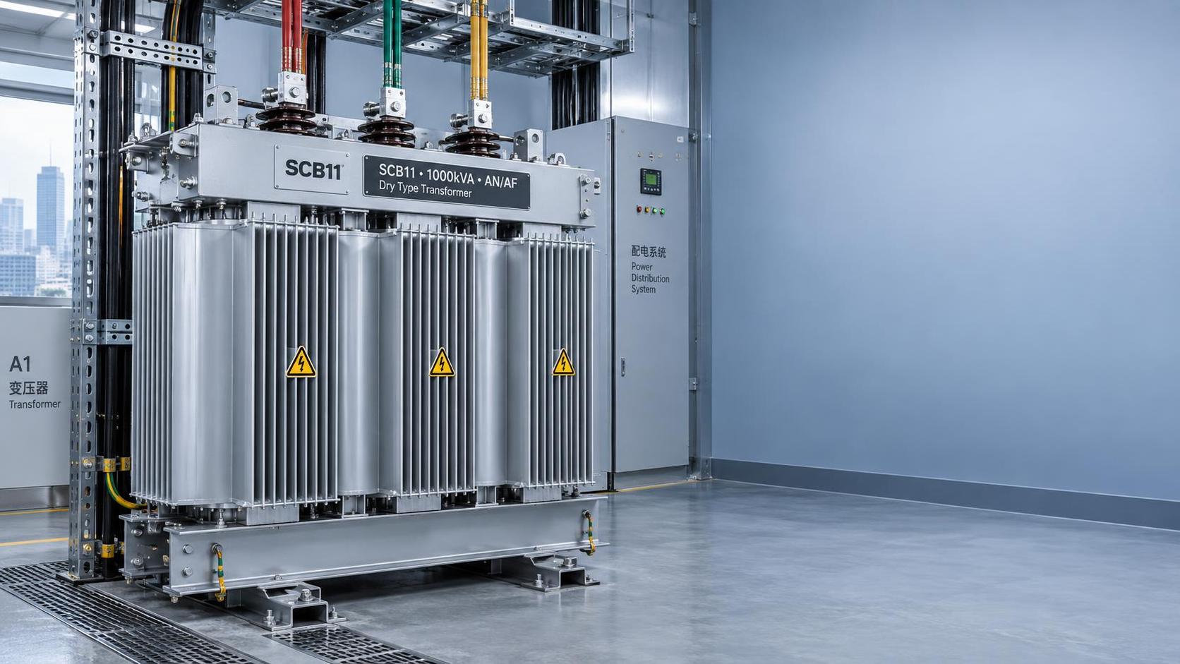
Installing an indoor transformer in a data center vault demands more than mechanical placement—it requires precise alignment with electrical safety, thermal management, and regulatory compliance. When clearance is insufficient, ventilation inadequate, or arc-flash boundaries unverified, the risk isn’t just equipment failure: it’s unplanned downtime, personnel injury, or fire propagation in a mission-critical environment. For quality control and safety personnel, this isn’t a one-time setup task—it’s a recurring verification point where NFPA 70E compliance, IEEE C57.12.00 clearance thresholds, and ASHRAE ventilation guidelines converge into actionable criteria.
Why Clearance Isn’t Just About Space—It’s About Arc-Flash Mitigation
Minimum clearance around indoor transformers directly impacts arc-flash incident energy calculations under NFPA 70E. Insufficient working distance reduces the time available for protective devices to operate and increases exposure risk during maintenance or fault conditions. IEEE C57.12.00 specifies nominal clearances based on voltage class and insulation type—not ambient temperature or enclosure design. For example, a 15 kV dry-type unit requires ≥914 mm (36 in) horizontal clearance from grounded surfaces and ≥1219 mm (48 in) vertical clearance above combustible materials. These distances assume standard ambient conditions; reductions are not permitted unless validated by arc-flash study and documented engineering justification.
What often gets overlooked is how transformer geometry interacts with these values. A unit with protruding bushings or terminal boxes may require additional lateral space beyond the base footprint. Likewise, rear-access designs necessitate clearance behind—not just in front—of the unit. If your vault has fixed conduit runs, structural columns, or adjacent switchgear, verify clearance at *all* access points—not just the primary service side.
Ventilation: Thermal Load ≠ Airflow Guarantee
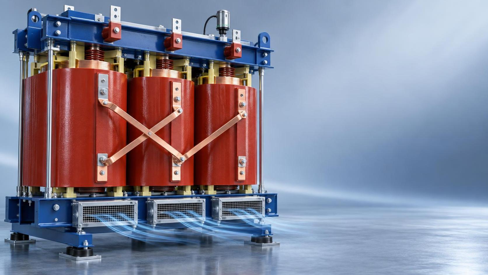
Data center vaults prioritize containment, but that works against transformer cooling. Dry-type units rely on natural or forced convection—not oil circulation—to dissipate heat. ASHRAE Technical Guidelines for Datacom Equipment specify minimum airflow rates per kW of loss, but those assume unrestricted inlet/outlet paths and stable ambient gradients. In practice, vaults with sealed walls, recessed mounting, or stacked configurations create recirculation zones where hot air re-enters the intake. This leads to localized hotspot formation—even when nameplate temperature rise appears within limits.
Key checks before energization:
- Confirm inlet grilles are unobstructed and sized for full-rated airflow—not just nominal transformer rating. Derate for filter loading and duct friction loss.
- Verify outlet path terminates outside the vault or into a dedicated exhaust plenum—not into shared ceiling cavities.
- Measure ambient temperature at both inlet and outlet locations during peak load simulation. A delta-T exceeding 15°C signals inadequate flow or recirculation.
NFPA 70E Compliance: Beyond Labeling
An arc-flash label is necessary—but insufficient. NFPA 70E mandates site-specific hazard analysis, including shock protection boundary calculation, PPE selection matrix, and documented justification for any reduced approach boundaries. For indoor transformer installations, this means verifying that the manufacturer’s published incident energy values correspond to actual system fault current—not utility-side assumptions. Many vaults feed from upstream breakers with adjustable trip settings; if those settings change post-installation, the original arc-flash study becomes invalid.
Also critical: grounding continuity. IEEE Std 142 recommends ≤5 Ω ground resistance for indoor substations, but what matters more is low-impedance bonding between transformer tank, enclosure, bus supports, and grounding electrode system. Use a low-resistance ohmmeter—not a standard multimeter—to validate connections. Resistance >1 Ω between any two bonded components indicates corrosion, loose hardware, or paint interference—common in epoxy-coated enclosures.
Material & Design Considerations for High-Risk Environments
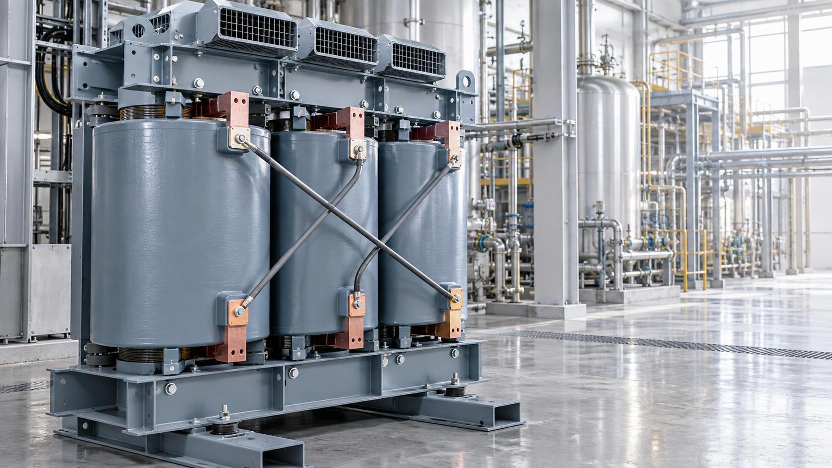
In flammable or explosive environments—such as server rooms adjacent to fuel storage, battery banks, or chemical handling areas—standard dry-type construction may not meet fire protection requirements. Epoxy resin–cast units like the SCB14 Type Dry-Type Transformer provide inherent flame retardancy, moisture resistance, and dust sealing without external enclosures. Their ability to be installed deep within load centers reduces cable run lengths—and associated voltage drop and fault energy—while maintaining compliance with GB20052-2020 Level 2 efficiency standards.
These characteristics matter operationally: no periodic oil sampling, no dielectric fluid containment, and no fire suppression system integration required beyond standard vault sprinklers. But they don’t eliminate the need for clearance or ventilation validation—only shift the risk profile toward thermal stability rather than fluid-related hazards.
Verification Sequence Before Energization
Don’t treat commissioning as a final sign-off. Build verification into each phase:
- Pre-mounting: Confirm vault dimensions match transformer shipping envelope—including lifting lugs, seismic brackets, and terminal extensions.
- Post-mounting, pre-wiring: Measure all clearances with calibrated tape; photograph and annotate deviations. Cross-check against IEEE C57.12.00 Table 11.
- Post-wiring, pre-energization: Validate grounding continuity, ventilation path integrity, and arc-flash label accuracy against updated short-circuit study.
- Post-energization, under load: Record surface temperatures at 25%, 50%, 75%, and 100% load over 4 hours. Surface rise >115°C at rated load warrants airflow review—even if winding temperature remains within limits.
When Standard Practices Fall Short
Some vaults have non-negotiable constraints: ceiling height under 3 m, floor loading limits below 5 kN/m², or adjacent HVAC ductwork that cannot be rerouted. In these cases, clearance or ventilation compromises must be justified—not waived. Options include:
- Specifying units with extended creepage distances to allow reduced air gaps (per IEC 60076-3), provided insulation coordination is revalidated.
- Integrating low-noise, high-efficiency forced-air cooling with thermostatically controlled fans—only if vibration isolation prevents resonance with nearby racks.
- Using amorphous alloy cores to lower no-load losses by up to 75%, reducing steady-state heat output without sacrificing short-circuit strength.
None of these alternatives bypass code requirements—they shift the burden of proof to documented engineering analysis. If your internal QC process lacks arc-flash modeling software or thermal imaging capability, engage a third-party reviewer before final sign-off.
For quality and safety teams, indoor transformer installation isn’t about checking off a list—it’s about confirming that every physical, thermal, and electrical parameter aligns with the operational reality of the vault. That alignment starts before delivery and continues through first load. When clearance, ventilation, and arc-flash boundaries are treated as interdependent variables—not isolated specs—the result isn’t just compliance. It’s sustained reliability where it matters most.


 Dry-Type Transformer Advantages for Hazardous Areas: Why IEEE C57.12.06 Arc Resistance & VPI Process Matter in Chemical Plants
 Air-Cooled Transformer vs Forced-Oil-Cooled: When Natural Convection Meets Thermal Load Peaks in Mining Substations
 SCB13 Dry-Type Transformer Long Lifespan: How Epoxy Resin Quality, Winding Stress Analysis & Ambient Humidity Monitoring Extend Service Life Beyond 30 Years
") S20 Oil-Immersed Transformer Quotation Breakdown: What 5 Line Items Actually Drive Total Installed Cost (Not Just kVA Price)
S20 Oil-Immersed Transformer Quotation Breakdown: What 5 Line Items Actually Drive Total Installed Cost (Not Just kVA Price) SCB11 Compact Dry-Type Transformer: Space-Saving Design Trade-Offs in High-Rise Building Electrical Rooms
 S11 vs S13 Oil-Immersed Transformers: Quantifying Efficiency Gains, Payback Period & Thermal Stability in Grid-Tied Substations
GET A FREE QUOTE
We offer reliable products, competitive prices, and nationwide professional support, committed to providing customers with efficient and energy-saving power equipment solutions.