


Selecting the right industrial control transformer for 24V DC systems isn’t about matching voltage ratings—it’s about managing dynamic load behavior. Relay chatter and PLC input dropout aren’t random failures; they’re symptoms of sustained voltage sag during inrush events, often misdiagnosed as faulty components or software glitches. When a bank of solenoids energizes simultaneously—or a group of safety relays cycles at machine startup—the transformer must supply peak current without dropping below 21.6V (90% of nominal) for more than 10–20 ms. Under-sized units collapse under this demand, causing contacts to bounce and digital inputs to misread or reset. Over-sizing, meanwhile, introduces unnecessary cost, larger footprint, higher no-load losses, and reduced efficiency at partial loads—especially problematic in systems running continuously with low average demand.
Why Standard VA Ratings Fail in Real Control Circuits
Most engineers begin sizing by summing the nameplate VA ratings of all connected devices: PLC power supplies, relay coils, indicator lamps, and signal conditioners. But this method consistently overestimates required capacity—because it ignores two critical realities. First, not all loads energize simultaneously. A typical packaging line may have 48 relay coils rated at 2.5 VA each, but only 12–16 are active during any given operational phase. Second, coil inrush current is transient and highly nonlinear: a 24V DC relay coil may draw 3–5× its steady-state current for 15–30 ms at closure. Transformer impedance limits how quickly it can respond to that surge. If the unit’s short-circuit impedance is too high—or its thermal mass too low—it cannot sustain the voltage dip long enough for the relay armature to fully seat, resulting in chatter.
This mismatch becomes acute when using switching-mode power supplies (SMPS) downstream of the transformer. SMPS draw near-sinusoidal current from the AC side, but their input rectifier-capacitor stages create sharp, narrow current pulses. These pulses stress the transformer’s winding reactance and increase harmonic heating—particularly in units not designed for non-linear loads. Standard dry-type transformers sized solely on RMS VA often run 15–25°C hotter than expected under real control-panel conditions, accelerating insulation aging and reducing service life.
The Three-Step Sizing Workflow for Stability
Reliable operation demands a sizing approach grounded in timing, thermal margin, and waveform fidelity—not just steady-state VA. Follow these steps in sequence:
- Identify the worst-case inrush group: Map all devices that energize within ±50 ms of each other during normal operation (e.g., main contactor + safety relays + emergency stop monitoring). Exclude devices triggered by separate logic paths or time delays. For each device, obtain the peak inrush current (not holding current) and duration from manufacturer datasheets—not generic tables.
- Calculate effective kVA demand: Multiply the total peak inrush current (A) by the secondary AC voltage (e.g., 120V or 240V), then divide by 1000. Apply a derating factor of 1.25 for harmonics if >30% of the load consists of SMPS or VFD control power supplies. This gives your minimum required kVA rating—not VA.
- Verify thermal and voltage regulation performance: Select a transformer with ≤4% impedance (Z%) at rated load. Confirm its temperature rise rating is ≤115°C (class H insulation) and that it meets IEC 60076-11 or GB/T 6451-2008 for dry-type units. Units with higher thermal mass and lower Z% recover faster between surges, preventing cumulative voltage depression across sequential operations.
Where SCB18 Meets Control-Critical Requirements
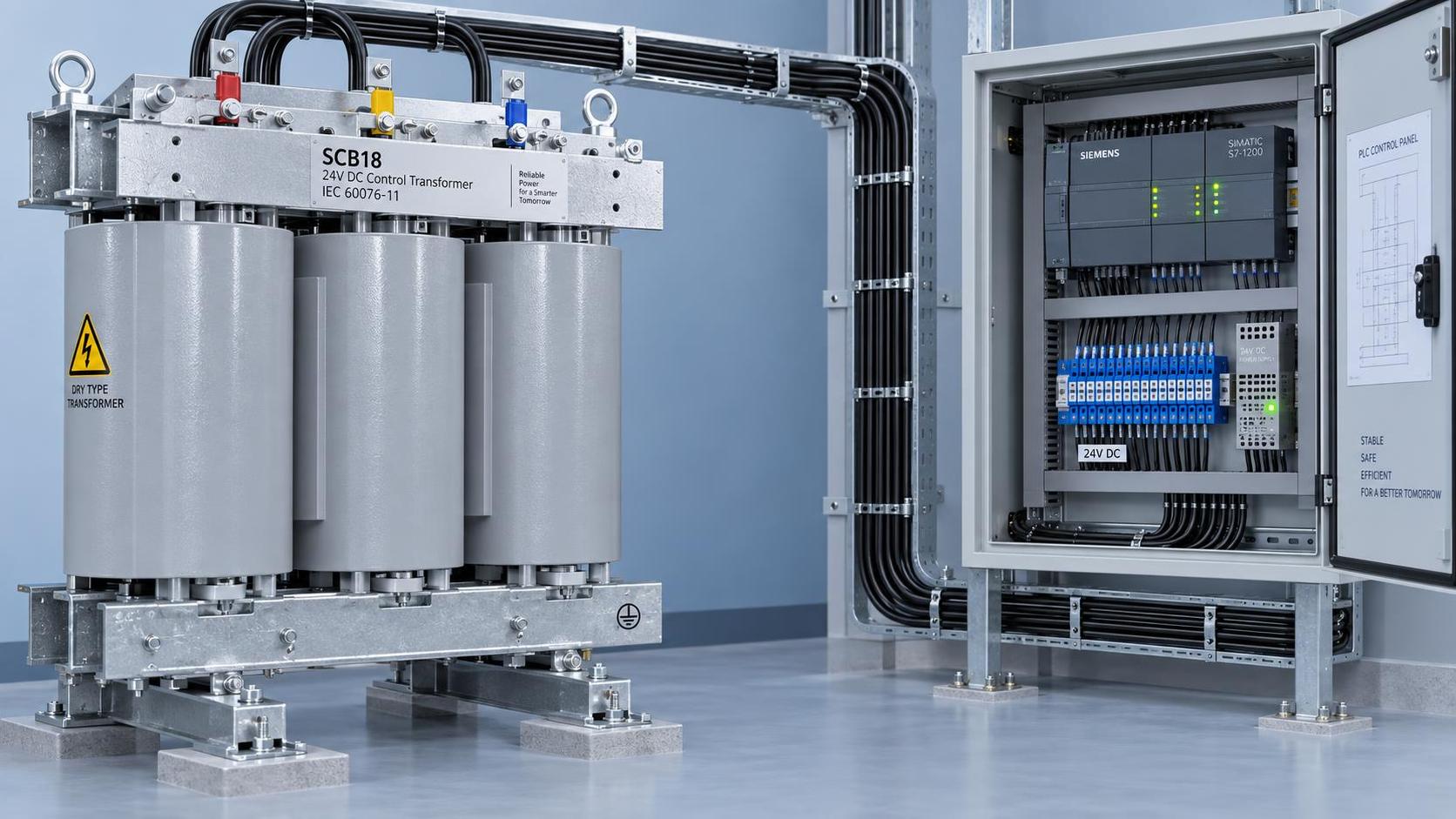
For applications where reliability, fire safety, and consistent voltage regulation are non-negotiable—such as control rooms in power plants, railway signaling cabinets, or automated assembly cells—the SCB18 Type Dry-Type Transformer delivers measurable advantages. Its epoxy resin cast construction provides inherent flame retardancy and moisture resistance, eliminating concerns about oil containment or ventilation in confined spaces. More critically, its optimized winding geometry achieves a typical impedance of 3.8%, allowing faster recovery from repeated inrush events without compromising short-circuit withstand capability. The design also minimizes stray flux, reducing electromagnetic interference with nearby PLC backplanes and analog sensor wiring—a frequent contributor to unexplained input noise or false triggering.
Unlike older SCB10 or SCB13 models, the SCB18 incorporates refined core lamination stacking and improved cooling duct layout, resulting in up to 12% lower no-load losses at 25% loading—a significant advantage in 24V DC systems where control power remains energized 24/7. Its low acoustic noise (<55 dB at 1m) further supports installation directly inside operator cabins or control centers, avoiding costly external enclosures or remote mounting.
Field Checks Before Commissioning
Even with correct sizing, field conditions can undermine performance. Conduct these checks before final handover:
- Measure actual secondary voltage under full inrush: Use a true-RMS oscilloscope (not a multimeter) to capture voltage waveform at the transformer output terminals during worst-case energization. Look for dips exceeding 10% lasting >20 ms.
- Verify cable voltage drop: Calculate voltage loss from transformer to first distribution point using conductor size, length, and peak current. Exceeding 1.5% drop here negates precise transformer sizing.
- Confirm grounding continuity: A floating or high-impedance ground reference between transformer secondary and PLC chassis can cause common-mode noise that mimics input dropout. Measure resistance from transformer neutral to PLC ground bus—it must be <1 Ω.
- Check for shared neutrals: Never tie the neutral of a control transformer to the neutral of a main power transformer serving motors or lighting. Ground loops and circulating currents will destabilize 24V DC regulation.
When to Reconsider the Architecture
If voltage stability remains elusive despite correct transformer selection and field verification, the issue may lie upstream. Consider these alternatives before replacing the transformer:
- Decouple high-inrush loads onto a dedicated control transformer—especially if relays and PLCs operate on independent timing cycles.
- Replace legacy electromechanical relays with solid-state equivalents where timing tolerance allows; their inrush is negligible compared to coil-based units.
- Evaluate whether a regulated 24V DC power supply—with built-in hold-up capacitors and inrush limiting—is more appropriate than an unregulated transformer + rectifier + capacitor bank for sensitive logic inputs.
Industrial control reliability hinges on understanding how components behave under transient conditions—not just their static ratings. Proper industrial control transformer sizing bridges that gap between theoretical specification and real-world stability. It requires attention to timing, impedance, thermal design, and system-level grounding—not just VA math. With standards-compliant units like the SCB18 Type Dry-Type Transformer, project managers gain a verified foundation for uninterrupted automation performance, aligned with ISO9001 quality discipline and GB/T6451-2008 compliance.


 Industrial Control Transformer Sizing Rules: Preventing Relay Chatter & PLC Input Dropout in 24V DC Systems
 Dry-Type Transformer Advantages for Hazardous Areas: Why IEEE C57.12.06 Arc Resistance & VPI Process Matter in Chemical Plants
 Air-Cooled Transformer vs Forced-Oil-Cooled: When Natural Convection Meets Thermal Load Peaks in Mining Substations
 SCB13 Dry-Type Transformer Long Lifespan: How Epoxy Resin Quality, Winding Stress Analysis & Ambient Humidity Monitoring Extend Service Life Beyond 30 Years
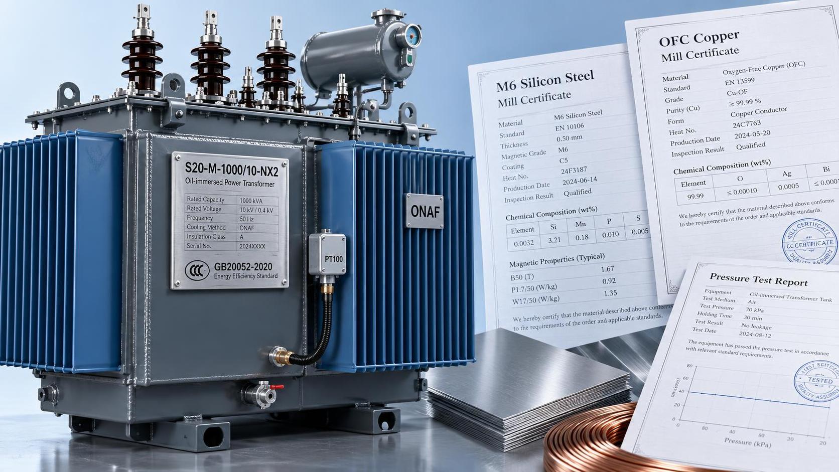
") S20 Oil-Immersed Transformer Quotation Breakdown: What 5 Line Items Actually Drive Total Installed Cost (Not Just kVA Price)
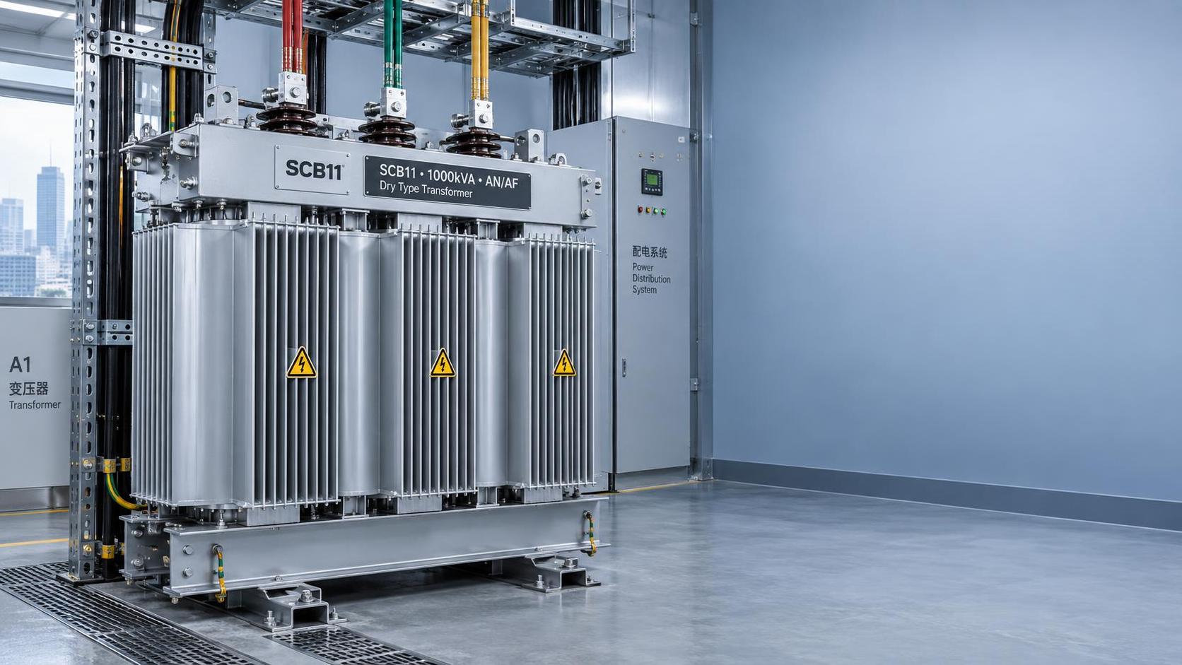
S20 Oil-Immersed Transformer Quotation Breakdown: What 5 Line Items Actually Drive Total Installed Cost (Not Just kVA Price) SCB11 Compact Dry-Type Transformer: Space-Saving Design Trade-Offs in High-Rise Building Electrical Rooms
GET A FREE QUOTE
We offer reliable products, competitive prices, and nationwide professional support, committed to providing customers with efficient and energy-saving power equipment solutions.