


Selecting a transformer is one of the decisions that turns a solar plant from a collection of generation equipment into a grid-connected project. It also affects procurement, civil design, protection studies and the connection schedule. S22 Series Oil-Immersed Power Transformers for solar power plants offer a low-loss option for stepping up voltage, but the series designation alone does not establish suitability. Project managers need to connect the transformer rating to inverter output, operating conditions and the utility’s requirements before specifications are released.
Start with the electrical path, not the transformer catalog
A solar plant may use several inverter stations, each feeding a transformer that raises the inverter output to a medium-voltage collection level. The collection system then connects to a substation and, where required, another transformer raises voltage to the grid connection level. The appropriate arrangement depends on plant size, inverter configuration and the network design.
Before asking for quotations, establish a preliminary single-line diagram showing inverter groups, transformer locations, collection circuits and the point of connection. Confirm which equipment the utility owns, which voltage it requires and where metering and protection responsibilities begin. An unresolved boundary at this stage can become a costly redesign after equipment orders are placed.
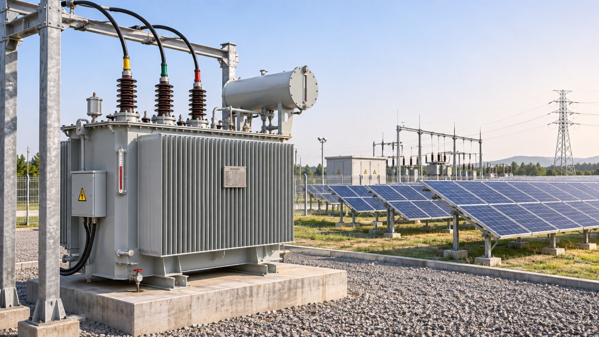
How to size an S22 transformer for solar generation
Transformer capacity is expressed in kVA or MVA, while solar project capacity is often discussed in MW or in DC module capacity. These figures are not interchangeable. Begin with the maximum expected AC output of the inverters served by each transformer, then consider the reactive power the plant must provide or absorb.
A useful preliminary relationship is apparent power (MVA) = active power (MW) ÷ power factor. For example, 5 MW delivered at a power factor of 0.95 corresponds to approximately 5.26 MVA. This is a starting point, not a final nameplate selection: the design must also account for inverter operating limits, auxiliary demand, ambient conditions and any required spare capacity. Check whether the utility’s reactive-power obligation applies at the point of connection, where network losses and other equipment also affect the calculation.
DC module capacity should not be used directly as the transformer rating. A plant may have more installed DC capacity than inverter AC capacity, while inverter controls may limit AC export. Conversely, reactive power can increase transformer current even when active export is capped. Review the inverter capability curve across the expected operating range rather than assuming that maximum MW and maximum reactive power will always occur together.
Allow for site conditions and future operating choices
High ambient temperatures, altitude and restricted cooling can affect permissible loading. Share the site design temperatures, elevation, ventilation arrangement and expected loading profile with the manufacturer so any rating adjustment is evaluated against the applicable standard. If expansion is planned, decide whether extra transformer capacity is justified now or whether an additional unit would better match the construction phases.
Solar output also varies through the day. A transformer remains energized during periods of little or no generation unless the operating strategy disconnects it. No-load losses therefore matter alongside load losses. Compare both using the project’s expected operating hours and energy value; choosing solely by purchase price can hide a material lifetime cost.
Grid connection details that deserve an early review
A transformer can be correctly sized and still delay energization if its electrical characteristics do not fit the network. Bring the utility, electrical designer and equipment supplier into the same discussion on these points:
- Voltage and taps: Confirm rated voltages, the expected grid voltage range and the required tap range and increments. Decide whether off-circuit adjustment is sufficient or whether the network study calls for on-load voltage regulation.
- Vector group and grounding: Agree on winding connection, phase displacement, neutral availability and grounding method. These choices affect fault-current paths and protection coordination.
- Impedance and fault duty: Transformer impedance influences voltage drop and short-circuit current. The selected value must fit both the plant design and the interrupting ratings of associated switchgear.
- Insulation and surge protection: Match insulation levels and surge arrester arrangements to the system voltage, utility requirements and site exposure.
- Protection and studies: Coordinate transformer protection with upstream and downstream devices. Inrush, earth faults, harmonics and inverter behavior should be addressed in the relevant studies.
These requirements should appear in the purchase specification, not remain as assumptions in separate engineering files. Request the transformer data needed for load-flow, short-circuit and protection studies early enough for the design team to check it before manufacturing details are frozen.
Oil-immersed outdoors, dry-type where the layout calls for it
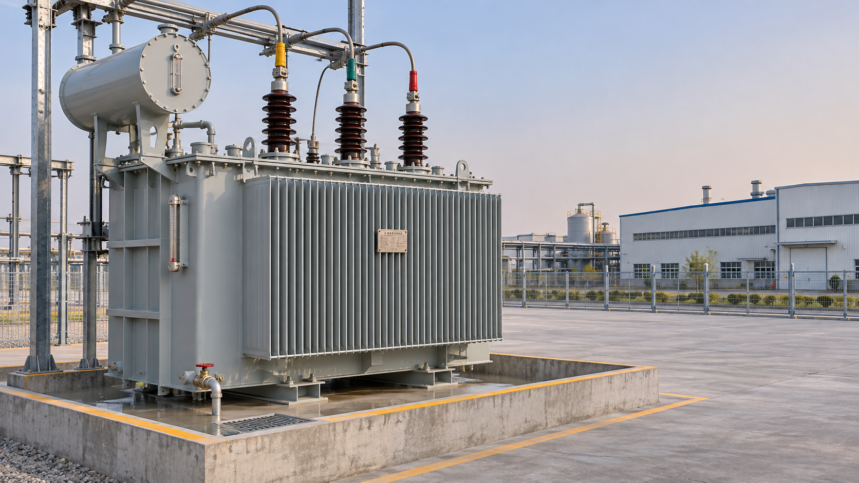
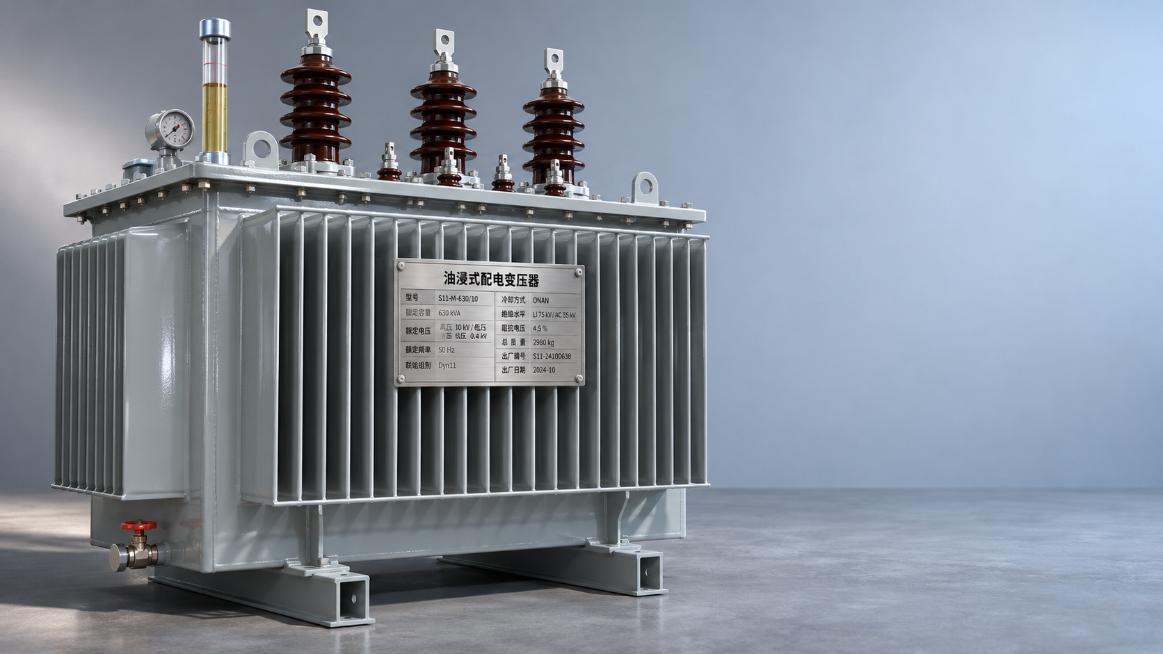
For an outdoor solar installation, an oil-immersed unit requires a practical plan for access, oil containment, drainage and fire separation under local rules. Consider transport dimensions, lifting points, foundation loads and the route maintenance crews will use after the site is built. A unit that fits electrically but cannot be safely installed or serviced is not a good project fit.
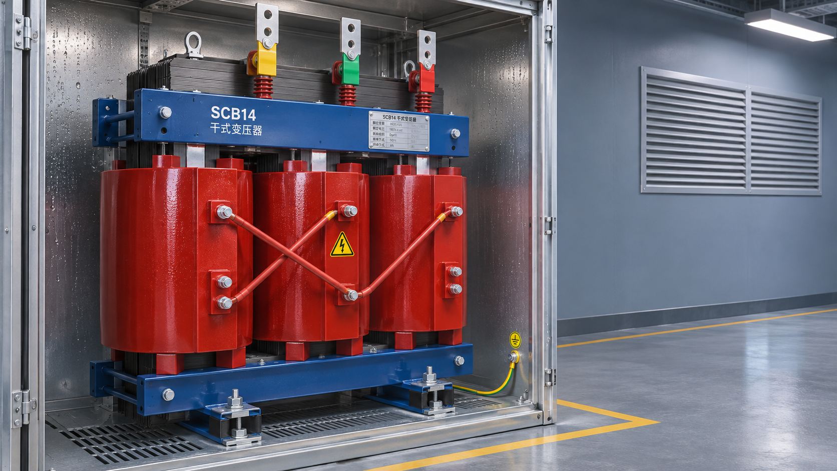
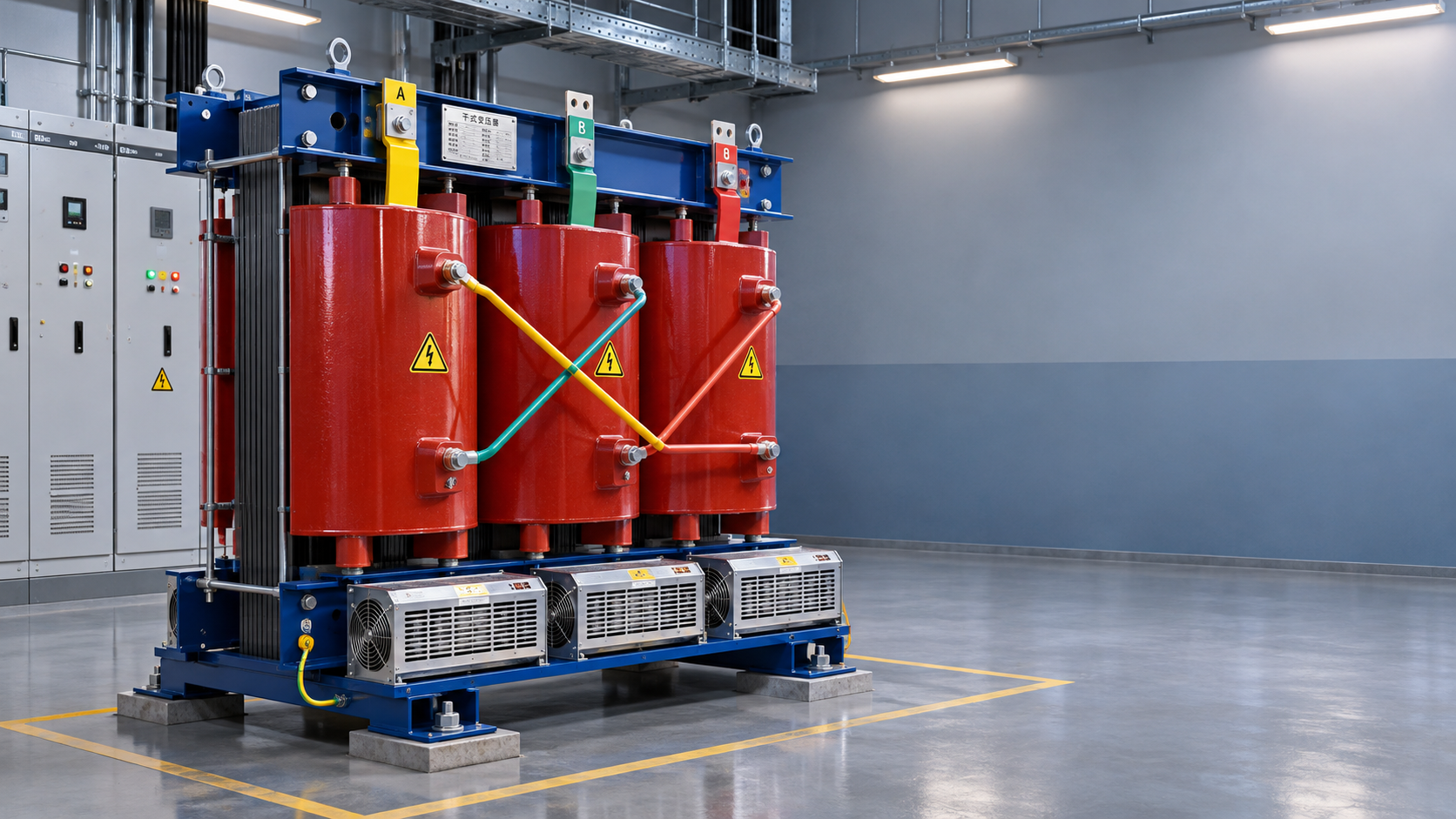
Some associated buildings or substations may instead call for a dry-type solution because of their fire-protection requirements or proximity to load centers. The epoxy-resin-cast SCB18 Type Dry-Type Transformer is an option to assess for such locations. Its characteristics include low loss and noise, flame retardancy, and resistance to moisture and dust. It should be selected against the actual voltage, rating, ventilation and environmental requirements rather than treated as an automatic substitute for the plant’s oil-immersed transformer.
Turn the specification into a procurement checkpoint
Before releasing the order, align the single-line diagram, inverter schedule, grid-connection requirements and civil layout. The enquiry should state capacity, voltage ratio, frequency, vector group, impedance, tapping, cooling, insulation requirements and site conditions. It should also define required routine and, where applicable, additional tests, documentation, delivery interfaces and applicable standards. Ask suppliers to identify deviations explicitly so bids can be compared on the same basis.
Jiangsu Shengda Power Equipment Co., Ltd. supplies low-loss transformer series including S22, as well as 10 kV and 35 kV models and related substation equipment. For a project team, the useful next step is to share the preliminary electrical data and connection requirements with the supplier and electrical designer together. That gives sizing questions, manufacturing constraints and utility comments a chance to surface while the schedule still has room to respond.



 Where Can S22 Oil-Immersed Transformers Fit in Distribution Projects?
 Evaluating S20 Transformer Exporters: Documentation and Delivery Risks
 Protecting SCB14 Dry-Type Transformers From Moisture and Condensation
 Requesting an SCB18 Transformer Quote: Specifications to Include
 S20 Transformer Ratings Explained: Capacity, Losses and Impedance
 ZGS Combined Substation Cost: Equipment, Civil Works and Installation
GET A FREE QUOTE
We offer reliable products, competitive prices, and nationwide professional support, committed to providing customers with efficient and energy-saving power equipment solutions.