


Why “Compact” Isn’t Just About Dimensions — Real Trade-Offs for SCB11 Type Dry-Type Transformer Deployment in High-Rise Electrical Rooms
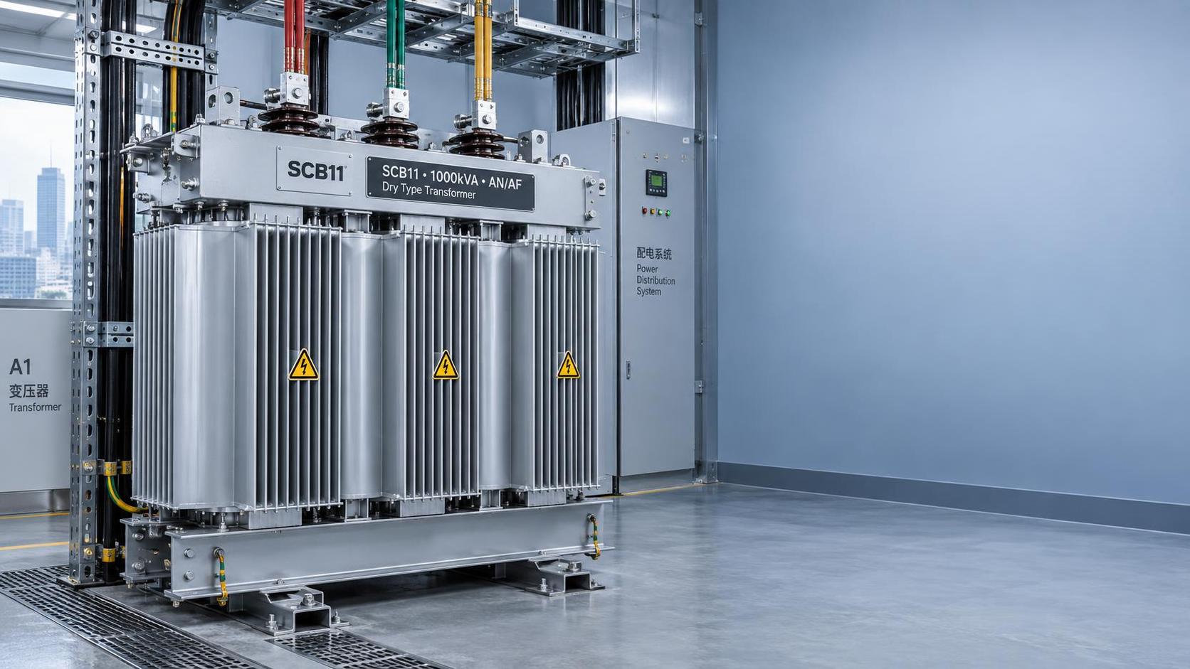
For project managers, selecting a transformer for a high-rise building isn’t about finding the smallest unit that fits on paper. It’s about verifying whether its compact design delivers *sustained, safe, and maintainable* performance under real-world constraints: limited floor-to-floor height, tight clearances around adjacent switchgear, restricted ventilation paths, and strict noise limits in occupied zones above or below the electrical room. The SCB11 Type Dry-Type Transformer compact design is frequently specified for exactly this scenario — but its footprint reduction comes with engineering consequences that must be explicitly evaluated, not assumed.
Cooling Efficiency vs. Physical Density: The Core Constraint
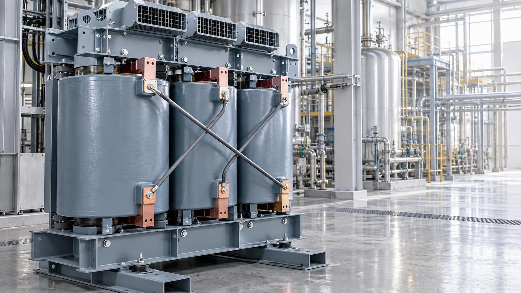
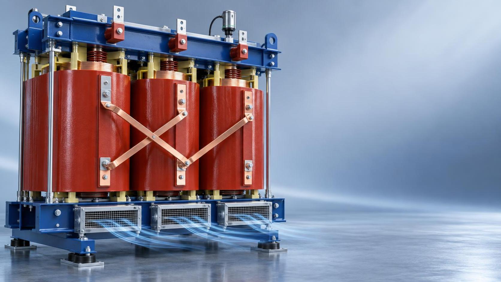
Dry-type transformers rely entirely on natural or forced air convection to dissipate heat generated during load operation. Reducing physical volume inevitably compresses the cooling path: narrower ducts between windings, tighter spacing between cooling fins, and less surface area exposed to ambient airflow. In an SCB11 Type Dry-Type Transformer compact design, this compression directly impacts temperature rise — a critical parameter defined in GB/T6451-2008 and GB1094.1-2-1996. A transformer rated at 1000 kVA in a standard footprint might achieve a 100 K average winding temperature rise at full load under natural convection. The same rating in a compact version may require forced-air cooling (AF) to stay within the same limit — or, if forced cooling is omitted, may need to be de-rated to 800 kVA to meet the standard’s thermal class requirements.
This isn’t theoretical. In actual high-rise deployments, we’ve seen projects where compact units were installed without verifying local airflow velocity and ambient temperature profiles — leading to repeated thermal alarms, accelerated insulation aging, and premature failure of fan-assisted cooling systems. The takeaway: “compact” does not mean “self-cooling at full rating.” Always request the manufacturer’s certified temperature rise data *under the intended cooling mode* (AN or AF), and cross-check it against the actual air exchange rate and maximum ambient temperature in your specific electrical room layout.
Maintenance Access: Where “Space-Saving” Can Become “Access-Blocking”
A transformer isn’t just installed — it’s inspected, tested, cleaned, and occasionally repaired. Compact designs often minimize clearance on all sides to reduce overall footprint. But standards like GB/T10228 and JB/T10088-2016 implicitly assume minimum working space for safety and serviceability: 600 mm front access for terminal inspection, 300 mm rear clearance for ventilation, and unobstructed vertical headroom for lifting and winding inspection. When an SCB11 Type Dry-Type Transformer compact design is squeezed into a 2.4 m wide shaft or placed directly against a fire-rated wall, those clearances vanish.
The result? Technicians forced to work in confined positions, increased risk of accidental contact with live parts during routine IR thermography, and inability to perform partial discharge (PD) testing — a key predictive maintenance indicator for dry-types. If PD levels rise undetected due to inaccessible test points, insulation degradation accelerates silently. So before finalizing the layout, physically mock up the unit with required clearances — not just the transformer outline. If the design forces technicians to remove adjacent panels or disconnect busbars just to reach a tap changer, the space saving has created a long-term operational liability.
Short-Circuit Withstand & Mechanical Rigidity: What Compression Does to Structural Integrity
During a fault, electromagnetic forces can exceed tens of kilonewtons. Standard SCB11 units use robust winding support structures and carefully engineered clamping pressure to contain these forces. In compact variants, reduced height or width often means shorter, stiffer winding stacks — which increases mechanical stress concentration at the ends. While all units must comply with short-circuit withstand requirements per GB1094.5, the margin between compliance and real-world resilience narrows when geometry is optimized purely for size.
Look beyond the pass/fail label. Ask for the calculated peak electromagnetic force distribution across the winding — especially for units operating near the upper end of the SCB11 series (e.g., 2500 kVA and above). If the manufacturer provides finite element analysis (FEA) reports showing localized stress exceeding 85% of material yield strength, that unit may survive the standard test pulse but won’t tolerate repeated through-faults over decades of service — a critical consideration in high-rise buildings where upstream protection coordination often allows multiple cycles before backup tripping.
When to Consider a Different Approach: The Role of Advanced Materials
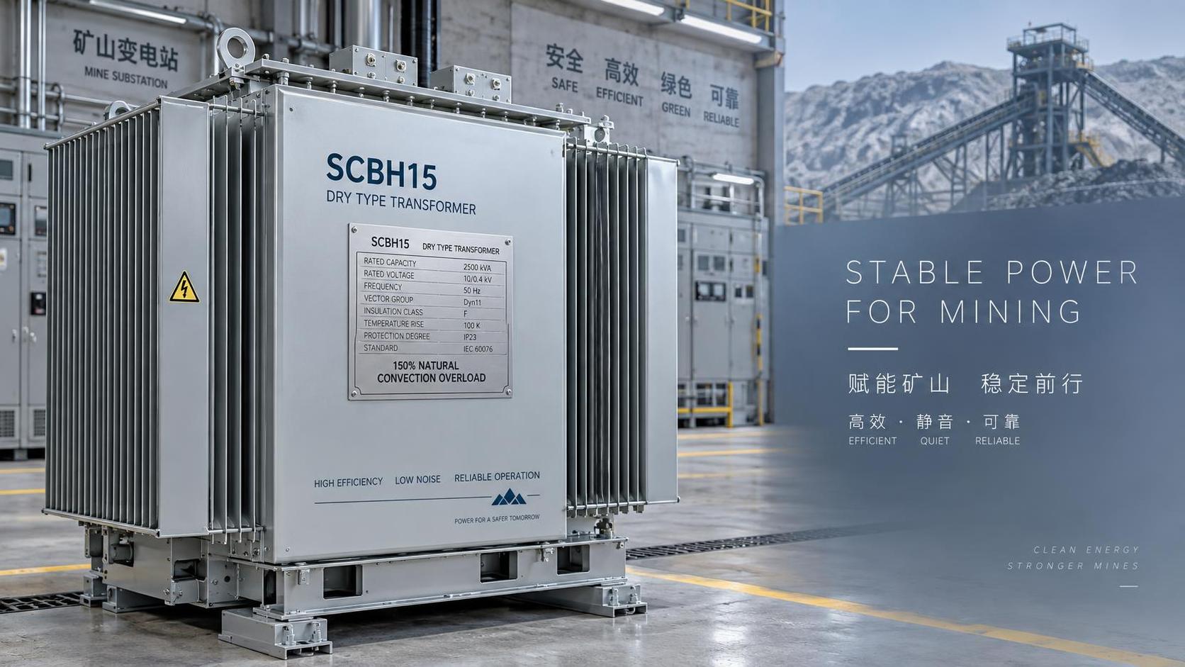
If your high-rise project demands both minimal footprint *and* uncompromised thermal headroom, higher efficiency, and extended service life, stepping beyond the SCB11 generation becomes technically justified. For example, amorphous alloy core technology — used in newer models like the SCBH15 Type Dry-Type Transformer — reduces no-load loss by more than 30% compared to SCB10 and achieves lower temperature rise under identical loading. Its inherently lower excitation current also contributes to reduced partial discharge and improved short-circuit withstand margin.
Crucially, this efficiency gain isn’t achieved by shrinking dimensions — it’s achieved by rethinking core losses at the material level. That means you retain serviceable clearances, avoid forced-air dependency for standard ratings, and gain operational flexibility: the SCBH15 Type Dry-Type Transformer is rated for continuous 150% load under air-cooled conditions, offering headroom for future tenant load growth without hardware replacement. This shifts the trade-off from “size vs. safety” to “initial cost vs. lifecycle value” — a far more actionable decision for project managers evaluating total cost of ownership.
Three Checks Before Finalizing Any Compact SCB11 Specification
- Ambient validation: Confirm measured max ambient temperature *at transformer location* — not just HVAC supply specs. Localized hot spots near cable trays or lighting fixtures often exceed design assumptions.
- Cooling mode verification: Ensure the specified cooling mode (AN/AF) matches the available airflow — and that AF fans are included, wired, and integrated into the BMS with fault reporting.
- Maintenance path audit: Walk through every scheduled maintenance task (IR scan, PD test, tap changer operation, cleaning) using the as-built layout. If any step requires disassembly of adjacent equipment, the design needs revision — regardless of how “compact” it looks on paper.
Ultimately, the SCB11 Type Dry-Type Transformer compact design solves a real spatial problem — but only if its compromises are acknowledged, quantified, and actively managed. Project managers who treat “compact” as a standalone feature, rather than a system-level constraint requiring coordinated thermal, mechanical, and operational validation, risk introducing reliability gaps that surface years after commissioning. The most space-efficient solution isn’t always the smallest box — it’s the one whose design boundaries align precisely with your building’s physical, thermal, and human realities.


 Dry-Type Transformer Advantages for Hazardous Areas: Why IEEE C57.12.06 Arc Resistance & VPI Process Matter in Chemical Plants
 Air-Cooled Transformer vs Forced-Oil-Cooled: When Natural Convection Meets Thermal Load Peaks in Mining Substations
 SCB13 Dry-Type Transformer Long Lifespan: How Epoxy Resin Quality, Winding Stress Analysis & Ambient Humidity Monitoring Extend Service Life Beyond 30 Years
") S20 Oil-Immersed Transformer Quotation Breakdown: What 5 Line Items Actually Drive Total Installed Cost (Not Just kVA Price)
S20 Oil-Immersed Transformer Quotation Breakdown: What 5 Line Items Actually Drive Total Installed Cost (Not Just kVA Price) SCB11 Compact Dry-Type Transformer: Space-Saving Design Trade-Offs in High-Rise Building Electrical Rooms
 S11 vs S13 Oil-Immersed Transformers: Quantifying Efficiency Gains, Payback Period & Thermal Stability in Grid-Tied Substations
GET A FREE QUOTE
We offer reliable products, competitive prices, and nationwide professional support, committed to providing customers with efficient and energy-saving power equipment solutions.