


Start with the load that actually matters
Most voltage drop problems begin before the transformer is ordered. The usual mistake is sizing from nameplate kW alone and ignoring how the machine behaves when it starts, accelerates, heats, or cycles under load. If you are choosing a step-up transformer for machinery, the first job is to map the real electrical demand, not the brochure figure.
For a project manager, that means collecting four things from the equipment package: rated voltage, full-load current, starting method, and duty pattern. A conveyor with a soft starter is one discussion. A hydraulic unit with direct-on-line motor starting is another. A machine that runs steadily all day can often be sized differently from one that hits repeated starts every few minutes.
If your team only has motor power in kW, do not stop there. Ask for the motor list, VFD list, heater loads, control transformer loads, and any auxiliary systems that start at the same time. In real projects, voltage sag often comes from the “small” loads nobody added together.
Check the startup condition before you check the steady-state rating
A transformer that looks fine on paper at normal running load can still cause nuisance trips or failed starts if the inrush and motor starting current were ignored. This is where many machinery projects get caught. The transformer may carry the continuous kVA, but the voltage dips too far during starting, so contactors chatter, drives fault, or the motor takes too long to come up to speed.
Use this check sequence:
- Identify which motors can start simultaneously.
- Confirm the starting method: DOL, star-delta, soft starter, or VFD.
- Review any load that creates a short, sharp current demand, such as compressors, pumps, crushers, or hoists.
- Ask the machinery supplier what minimum terminal voltage is required during startup for stable operation.
That last point matters more than people think. You are not trying to eliminate all voltage drop. You are trying to keep the drop within what the machine can tolerate. If the process line can ride through a brief sag, your sizing window is wider. If the controls, relays, or motors are sensitive, the transformer margin needs to be larger.
Do not treat cable distance as a side note
On machinery installations, voltage drop is often blamed on the transformer when the real issue is the feeder length and conductor sizing between transformer and load. A step-up transformer for machinery can be correctly selected and still perform badly if the outgoing run is long, undersized, or routed through a hot environment that reduces cable current capacity.
Review the one-line and layout early. Measure the practical cable route, not the neat drawing distance. Include vertical runs, tray routing, bends, and parallel conductors if used. Then evaluate the voltage drop at both full load and starting load. Many teams only calculate the full-load condition, which misses the event that actually causes trips.
If the transformer must sit far from the machine, you have three levers: increase transformer capacity, increase conductor size, or move the transformer closer. The cheapest purchase price is not always the lowest project cost once downtime risk and cable cost are included.
Size in kVA, then pressure-test the margin
Transformer selection should be driven by total apparent power and operating behavior, not by motor power alone. After you total the continuous load in kVA, test whether that number still works when the largest motor starts or when several loads come on together.
The practical question is simple: after normal load, starting load, and feeder drop are all considered together, does the machine still see acceptable voltage? If the answer is borderline, move up one size before the order is locked. Borderline designs tend to become site problems later.
Look at the source side, not only the machine side
A transformer cannot fix a weak upstream supply. If the incoming source already fluctuates, has limited short-circuit capacity, or is heavily loaded by other equipment, the secondary voltage performance will reflect that. This is a common blind spot on plant expansions, where the new machinery package is sized in isolation from the rest of the electrical system.
Before approving the transformer size, ask for the upstream transformer data, available source capacity, and any large neighboring loads that can switch during machinery startup. If the utility or plant bus is soft, adding transformer kVA alone may not solve the dip. You may need staged starting, a different starting method, or a revised distribution arrangement.
Match the transformer type to the installation risk
For machinery projects inside buildings, transport hubs, processing facilities, or high-occupancy sites, transformer type matters beyond simple voltage conversion. Fire performance, maintenance access, humidity exposure, and overload behavior all affect whether the selected unit will stay reliable in real service.
In applications where dry-type construction is preferred, a product such as Non-Encapsulated Dry-Type Transformer may fit projects that need a three-phase dry-type solution with flame-retardant and self-extinguishing characteristics, H-class insulation, and suitability for polluted or humid environments near lakes, seas, and rivers. For project teams comparing options, those details matter when the machinery area has heavy load cycles, stricter fire requirements, or difficult maintenance conditions.
This is also where supplier discipline counts. Manufacturers with established quality inspection systems and production control, and products built to declared standards such as GB1094.1-2-1996 and GB/T6451-2008, reduce the risk of getting a unit that meets paper requirements but behaves inconsistently on site.
Do not skip impedance and regulation discussions
When engineers talk about voltage drop, transformer impedance is usually in the background, but it should be in the front of the conversation. Impedance affects fault current and voltage regulation. Lower impedance can help reduce voltage drop under sudden load changes, but it also changes fault levels and protection coordination. Higher impedance may limit fault current, yet allow deeper voltage sag during motor starting.
This is not a place for generic assumptions. Ask for the transformer impedance value on the datasheet and check it against your startup study and protection settings. If your machinery supplier is sensitive to undervoltage, and your electrical team is tight on fault duty, that tradeoff needs to be resolved before procurement, not during commissioning.
Pay attention to harmonics, drives, and control stability
Modern machinery packages are rarely just motors and contactors. VFDs, PLC panels, rectifiers, servo systems, and heaters create a more complicated load profile. Even when the transformer kVA looks sufficient, harmonics and non-linear loading can add heat and create nuisance behavior in protective devices.
The practical check is to separate your load list into direct motor loads, drive-fed loads, resistive loads, and sensitive controls. Controls may need tighter voltage stability than the power section. If one transformer is feeding both heavy motors and delicate automation, you should be sure the control power arrangement can tolerate startup events. A line that restarts because the PLC dropped out is still a transformer sizing problem, even if the main motor eventually runs.
Use overload data carefully, not as a shortcut for undersizing
Some dry-type units offer strong overload capability. For example, SG(B)10 and SG(BY)10 series information may include long-term 120% overload capability and 140% overload for 3 hours under stated conditions. That is useful when the machinery duty cycle has controlled peaks. It is not a reason to buy too small a transformer for a system that will run near its limit all the time.
Treat overload capacity as operating resilience, not as your primary sizing method. If repeated starts, high ambient temperature, poor ventilation, and long feeder runs all exist together, the margin disappears quickly.
A short pre-order checklist saves long commissioning days
- Confirm required primary and secondary voltages, phase, and frequency from the machinery documents.
- Build a complete load schedule, including auxiliaries and control loads.
- Identify the worst starting scenario, not just the normal operating case.
- Calculate feeder voltage drop for actual installation distance.
- Review source strength and other upstream loads that may coincide.
- Check transformer impedance, temperature class, cooling conditions, and installation environment.
- Verify applicable manufacturing and quality standards in the supplier documentation.
- Freeze protection settings and transformer selection together, not as separate decisions.
If you need one rule to carry into procurement meetings, use this one: size the transformer for the machine’s hardest real operating moment, then confirm the cable run and source can support it. That is how you avoid the familiar pattern of “rated correctly, but still dropping voltage.” The best step-up transformer for machinery is not the one that only matches the nameplate. It is the one that starts cleanly, runs steadily, and leaves enough margin for the site conditions you actually have.


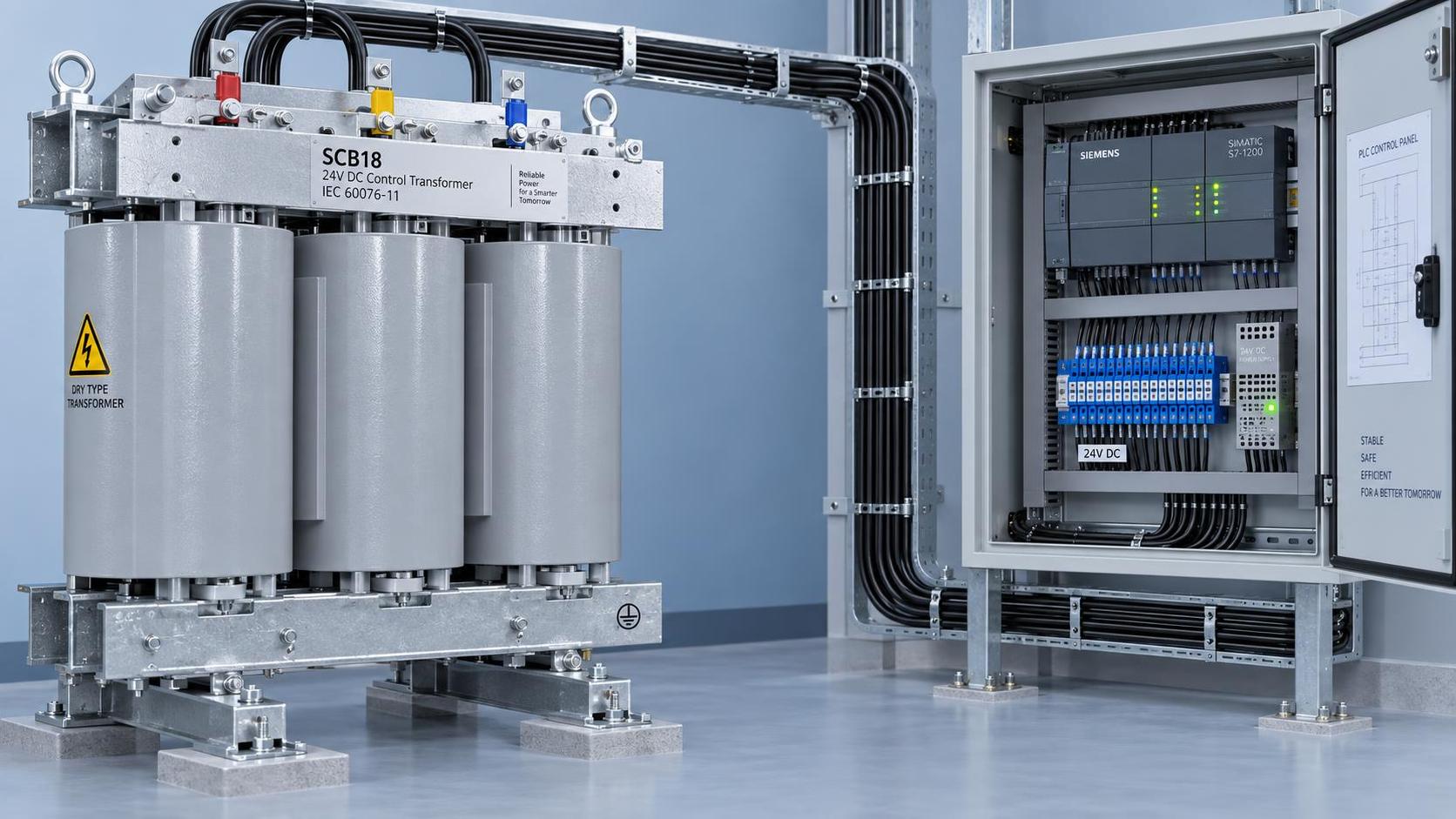
 Industrial Control Transformer Sizing Rules: Preventing Relay Chatter & PLC Input Dropout in 24V DC Systems
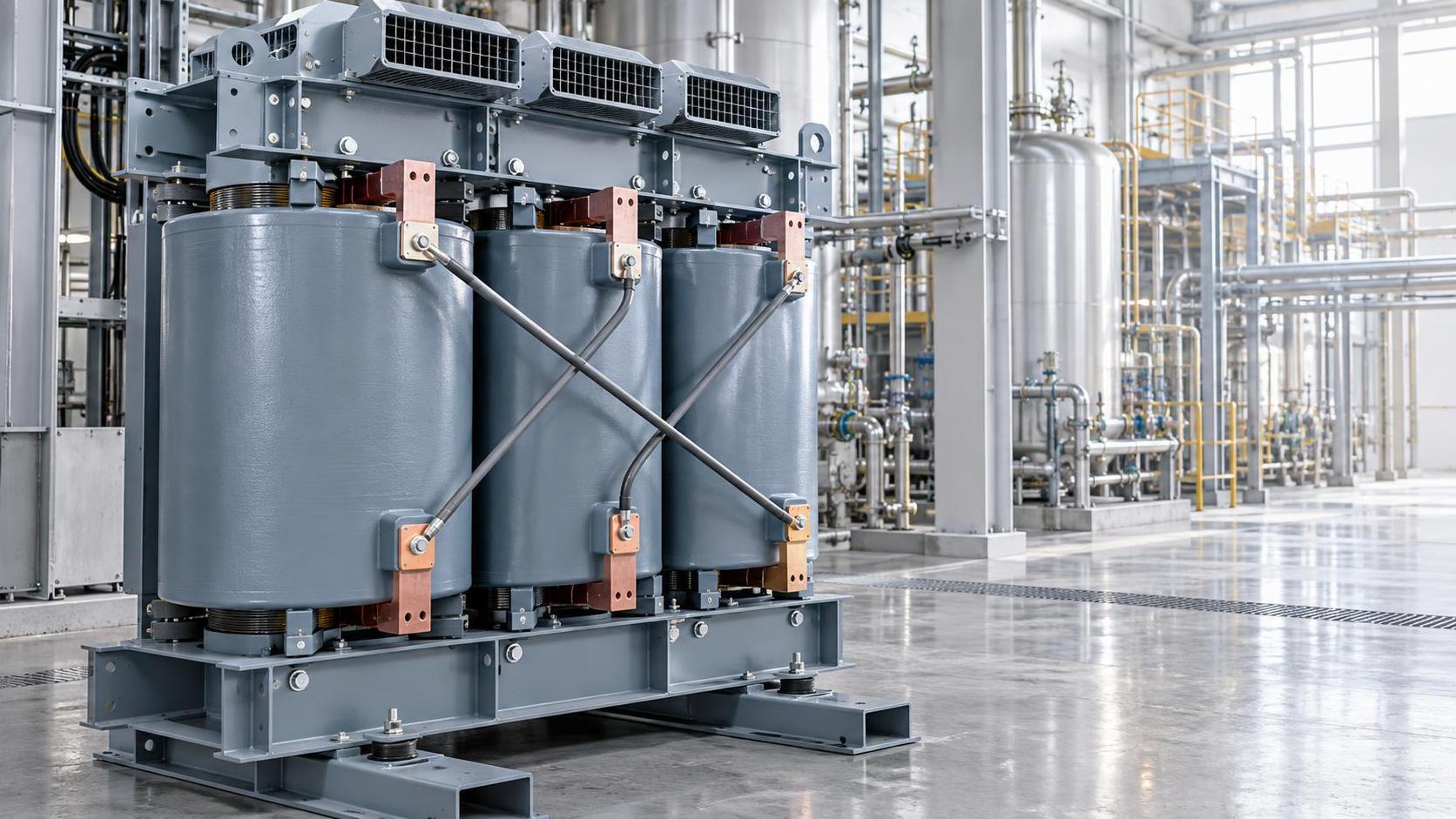
 Dry-Type Transformer Advantages for Hazardous Areas: Why IEEE C57.12.06 Arc Resistance & VPI Process Matter in Chemical Plants
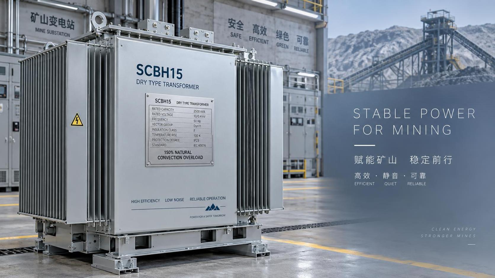
 Air-Cooled Transformer vs Forced-Oil-Cooled: When Natural Convection Meets Thermal Load Peaks in Mining Substations
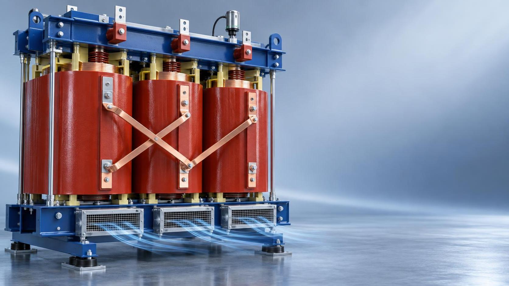
 SCB13 Dry-Type Transformer Long Lifespan: How Epoxy Resin Quality, Winding Stress Analysis & Ambient Humidity Monitoring Extend Service Life Beyond 30 Years
") S20 Oil-Immersed Transformer Quotation Breakdown: What 5 Line Items Actually Drive Total Installed Cost (Not Just kVA Price)
S20 Oil-Immersed Transformer Quotation Breakdown: What 5 Line Items Actually Drive Total Installed Cost (Not Just kVA Price) SCB11 Compact Dry-Type Transformer: Space-Saving Design Trade-Offs in High-Rise Building Electrical Rooms
GET A FREE QUOTE
We offer reliable products, competitive prices, and nationwide professional support, committed to providing customers with efficient and energy-saving power equipment solutions.